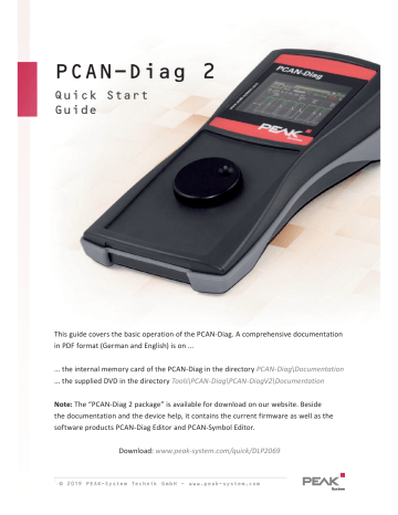
Peak PCAN-Diag 2 Quick Start Manual
Add to My manuals4 Pages
PEAK PCAN-Diag 2 is a powerful tool for analyzing and manipulating CAN bus data. With its intuitive user interface and comprehensive features, it's ideal for a wide range of automotive and industrial applications.
Connect to any CAN bus using the D-Sub connector and configure the bit rate manually or detect it automatically. Receive and transmit CAN messages, creating and managing transmit lists for automated communication.
Utilize the oscilloscope function to analyze incoming signals, triggering on specific events like CAN frame start or error. Adjust settings for signal sources and trigger conditions to capture and display waveforms.
advertisement

PCAN-Diag 2
Quick Start
Guide
This guide covers the basic operation of the PCAN-Diag. A comprehensive documentation in PDF format (German and English) is on ...
... the internal memory card of the PCAN-Diag in the directory PCAN-Diag\Documentation
... the supplied DVD in the directory Tools\PCAN-Diag\PCAN-DiagV2\Documentation
Note: The “PCAN-Diag 2 package” is available for download on our website. Beside the documentation and the device help, it contains the current firmware as well as the software products PCAN-Diag Editor and PCAN-Symbol Editor.
Download: www.peak-system.com/quick/DLP2069
© 2019 PEAK-System Technik GmbH - www.peak-system.com
Connectors
CAN connector (D-Sub)
... for connecting a High-speed, Low-speed, or Single-wire
CAN bus, depending on the integrated CAN transceiver.
PC connector (USB)
... for configuring the device with the PCAN-Diag Editor software and for accessing the internal memory card.
BNC connector
... for picking off a CAN-specific trigger signal by an external oscilloscope or for analyzing an external signal via measuring channel 2.
Switch interlock for push dial
... for securing the device for transport. If the toggle switch is up, the device is locked.
Voltage supply
... 12 V DC (8 - 50 V possible).
GND socket (4 mm)
... for establishing a separate ground connection between the PCAN-Diag and the device under test.
Operation
Voltage Supply
Set up the voltage supply with the supplied AC adaptor. Apply the appropriate plug adaptor to the AC adaptor (Euro, U.S., or UK). For mobile use, the PCAN-Diag can be supplied by batteries (also in the scope of supply).
Connecting to a CAN Bus
Connect the PCAN-Diag to a CAN bus via the CAN connector (D-Sub) on the rear of the device.
Turning on and Operating the Device
Hold down the push dial for at least half a second. The main menu appears after a blip and the splash screen. Any user input is done via a push dial:
Dial: Changes the selection or the value to be edited.
Press: Executes the selected function or sets the adjusted value.
© 2019 PEAK-System Technik GmbH - www.peak-system.com
Adjusting the CAN Bit Rate
To successfully establish a connection to a CAN bus, the bit rate used by the PCAN-Diag must correspond to the one on the bus. The setting is done in the
Device Settings area with one of the following entries:
CAN bitrate Manual selection of a bit rate from a list.
Detect CAN bitrate Automatic detection of the bit rate (only possible when there‘s CAN traffic on the connected bus).
Receiving and Transmitting
Displaying Incoming CAN Messages
Navigate to the CAN Data > Receive Messages menu entry. Incoming CAN messages are displayed as a list, sorted by the CAN ID (column ID). The representation of the CAN data bytes (D0…D7) is in hexadecimal format.
Transmitting CAN Messages
Navigate to the CAN Data > Manage Transmit Lists menu entry. Here you can create transmit lists with one or more CAN messages:
Enable the transmit list entry with the corresponding check box.
By clicking on the name, you can edit the transmit list. On this page you can insert single messages with I on the right side or edit an existing one with E .
Afterwards, edit the period for repeated transmission of the list in the
Cycle time(ms) column.
Close the page with Save&OK .
For the transmission of the list open CAN Data > Transmit Messages . Here you can start and stop the CAN transmission by clicking on the name of the list.
© 2019 PEAK-System Technik GmbH - www.peak-system.com
Oscilloscope Function
In order to analyze incoming signals with the oscilloscope function, select the Scope entry from the main menu.
Before first use, adjust the following settings for the oscilloscope in the Setting area, if needed:
Ch(1/2) source Selection of the signal sources to be viewed.
Trigger Selection of the event that triggers the sampling of the signals
(e.g. CAN frame start or end, CAN ID, CAN error, level).
After confirming the settings with Save&OK , you can start the recording and manipulate the view with the following functions:
Single
Run
Triggers a single recording of the signal.
Starts the repeated recording of the signal (end with Stop ).
Zoom / Delay Adjusts the view regarding the horizontal axis.
Device Configuration with Projects
The device and oscilloscope settings, CAN transmit lists, and the symbolic view of incoming CAN messages can be set up comfortably in form of projects on a PC with the software PCAN-Diag Editor; afterwards the projects are transferred to your PCAN-Diag via USB. You can find the program ( PcanDiagEdt.exe
) on ...
... the internal memory card of the PCAN-Diag in the directory: PCAN-Diag\Tools
... the supplied DVD in the directory: Tools\PCAN-Diag\PCAN-DiagV2\Tools
Comprehensive instructions about the creation of and the work with projects are in the user manual for the PCAN-Diag or in the program help of the PCAN-Diag Editor.
© 2019 PEAK-System Technik GmbH - www.peak-system.com
advertisement
Related manuals
advertisement