advertisement

1.5
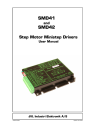
Connection of Motor
Terminate screen only for driver
Shield
Ground
Power
Error
1
2
3
4
5
Current Curve
Resolution
50kHz Filter ON/OFF
I
I
I
I
8
9
10
11
I
I
12
13
O 14
I
I
O
O
O
O
O
1
2
3
4
5
6
7
GND /
Supply
Motor A
Motor A
Motor B
Motor B
+
-
+
-
Power Dump
Direction
Stepclock
PNP
PNP
Digital GND
Standby Current
Move Current
Current GND
Error
TT0016GB
1.5.1
Cabling
For Driver models that supply a phase current in the range 0 to 6 A, it is recommended that 0.75mm² cable (minimum) is used to connect the motor to the Driver.
For Driver models that supply a phase current in the range 0 to 9 A, it is recommended that 1.5mm² cable is used to connect the motor to the Driver.
Cable lengths used to connect the motor to the Driver should not exceed 10 metres because of impedance loss.
Connected cables should be securely tightened since a poor connection can cause heating and destruction of the connector terminals. Similarly, tinned conductors should be avoided. The torque used for each screw is recommended in the range 0.22 - 0.25Nm.
Important!
To minimise spurious noise emission from the motor cables and fulfil CE requirements, screened cable must be used!
If screened cable is not used, other electronic equipment in the vicinity may be adversely affected.
The removable connector must never be removed while a voltage is connected as this will significantly reduce the lifetime of the connector. Note also that the connector’s lifetime is reduced by repeated connecting/disconnecting since the contact resistance of the pins is increased.
Note that GND (1) is connected to the chassis and functions as the main ground on the
SMD41/42.
See also
Motor Connections,
page 21, which describes how various models of motor should be connected to the SMD41/42.
JVL Industri Elektronik A/S — User Manual Step Motor Driver SMD41/42 11
1.5
Connection of Motor
Serial connection of phases:
Parallel connection of phases:
Motor
Torque
Parallel
Serial
Velocity
Current for Serial or Parallel connection
Maximum current settting
Example motor 4.2A
Motor
4-phase parallel
Motor
4-phase serial
Motor
2-phase
I x 1.41
1.41
4.2 x 1.41 =5.9
4.2
1.41
= 3A
4.2A
I = Nominal current per phase in accordance with manufacturer's specifications
TT0008
1.5.2
Connection of Step Motor
Various types of step motor are available:
1.
2-phase Bipolar (4 cables)
2.
4-phase Bipolar/Unipolar (8 cables)
3.
4-phase Unipolar (6 cables). Not suitable.
Note
that Type 3 motors indicated above (Unipolar motors) are not suitable for operation with this series of Drivers since the Drivers utilise the bipolar principle.
Note that a bipolar system typically yields 40% greater torque than unipolar systems.
2-phase or 4-phase motors can be connected to the Drivers as follows:
2-phase Motors
(4 cables).
This type of motor can be directly connected to the Driver’s output terminals.
The Driver current adjustment must not exceed the manufacturer’s specified rated current for the motor.
4-phase Motors
(8 cables).
This type of motor can be connected to the Driver in one of the 2 following ways:
1. Serial connection of phases.
2. Parallel connection of phases.
Selection of serial or parallel connection of the motor phases is typically determined by the speed requirements of the actual system.
If slow speeds are required (typically less than 1 kHz), the motor phases can be connected in serial. For operation at higher speeds (greater than 1 kHz), the motor phases can be connected in parallel.
12 JVL Industri Elektronik A/S — User Manual Step Motor Driver SMD41/42
1.5
Connection of Motor
Serial Connection
:
Using serial connection of the phases, a motor provides the same performance (up to
1kHz) as parallel connection, but using only approximately half the current. This can influence the selection of Driver model and enables a Driver rated for a lower motor current to be used. See illustration on previous page.
If the phases of a 4-phase step motor are connected in series, the motor’s rated phase current should be divided by 1.41. For example, if the rated current is 4.2A, the maximum setting of the Driver phase current must not exceed 3 A when the motor phases are connected in series.
Parallel Connection:
With parallel connection of motor phases, a motor will provide better performance at frequencies greater than 1kHz compared to serially connected phases, but requires approximately twice the current. This can influence the choice of Driver since it is necessary to select a Driver that can supply twice the current used for serial phase connection.
See illustration on previous page.
When the phases of a 4-phase motor are connected in parallel, the specified rated current of the motor must be multiplied by a factor of 1.41. For example, if the rated current is 4.2 A, the maximum setting of the Driver phase current must not exceed 5.9 A when the phases are connected in parallel.
It should be noted that the lower the self-induction of the motor the better since this influences the torque at high speeds. The torque is proportional to the current supplied to the motor.
The applied voltage is regulated by the Driver so that the phase current is adjusted to the selected value. In practice this means that if a motor with a large self-inductance (e.g.
100mH) is used, the Driver cannot supply the required phase current at high speeds (high rotational frequencies) since the output voltage is limited.
JVL Industri Elektronik A/S — User Manual Step Motor Driver SMD41/42 13
advertisement
Related manuals
advertisement