advertisement

1.13
Connection to Indexer SMI30
u
O4
O5
O6
O7
O8
O -
OE
O+
O1
O2
O3
P +
P -
AI1
A
B
AI2
AO1
DRIVER
SMI30 / 31
POWER
PROGRAM
MOTOR
ERROR
HM
PL
I
NL
I8
I7
I6
I
I5
I4
I3
I2
I
I1 RS232
RS485
Motor
A power-dump resistor may be mounted
(SMD41 : 33-50 Ohm/50W)
(SMD42 : 68-100 Ohm/50W)
+
Fuse T10A
Ground
Screen
Screen connected to digital GND as close to driver as possible
DRIVER
Screen
Power
Error
1
2
3
4
5
Current Curve
Resolution
50kHz Filter ON/OFF
I
I
O
O
O
O
1
2
3
4
5
6
I
I
O
I
7
8
9
10
I 11
I
I
12
13
O 14
GND /
Supply
Motor A
Motor A
Motor B
Motor B
+
-
+
-
Power Dump
Direction
PNP
Stepclock
PNP
Digital GND
Standby Current
Move Current
Current GND
Error
TT0017
Resistor values selected in accordance with table in section
"Adjustment of Motor Current”
2,2k
P+
SALA
COIN
SON
6
7
8
9
4
5
1
2
3
CLK-
CLK+
DIR-
DIR+
GND
1.13.1
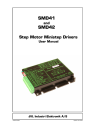
Connection to Indexer SMI30
The above illustration shows how a typical connection is made between the SMD41/42 and JVL Indexer SMI30 or SMI31. It is recommended that screened cable is used for connecting the motor and the logic signals to the SMI3x in order to avoid spurious noise problems and to fulfil the requirements of CE conformity for the complete system.
It is recommended that the cable length between the SMI3x and SMD41/42 does not exceed 2 m.
The following SMI3x registers must be set:
PR
Pulses per motor revolution. This register must be set according to the number of steps per revolution selected on the SMD41/42.
CB15
Control flag for SALA (servo alarm). This flag is set to CB15=1 so that the SMI3x accepts logic 0 as the active level for the SALA input. This means that the SMI3x detects any error from the SMD41/42 when the "Error" Output goes to logic 0.
JVL Industri Elektronik A/S — User Manual Step Motor Driver SMD41/42 23
advertisement
Related manuals
advertisement