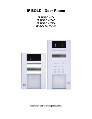
Relays connection. Alphatech IP Bold series, IP Bold - tx, IP Bold - tkxc, IP Bold - txc
Add to My manuals83 Pages
advertisement

1.4.2 Relays connection
Relay contacts connection (3) and (4) is on the picture. Marking " NO " menas in stand by open contact, " COM " means shared output (middle) and
" NC " means in stand by closed contact. Contacts of both relays are mutually galvanically isolated as same as isolated from othe IP BOLD components.
It is recommended use for IP BOLD PoE powering (according directive
IEEE802.3af) or AC voltage min.11V - max.15V or DC voltage min.12Vss - max.18Vss. which is connected to screw " 12V ". The IP BOLD consumption is max.300mA. This powering is possible simultaneously use for electrical lock(s) feeding. Then you have to consider el.lock consumption. In practise mostly used is AC / DC power supply 12V/1A÷2A.
IP BOLD - installation and operating instructions 15
Possibilities of relays connection are at following pictures:
16 IP BOLD - installation and operating instructions
IP BOLD - installation and operating instructions 17
1. Standard electrical lock connection. This connection is used most often.
One shared power supply feeding door entry IP BOLD and both electrical loch. Current loading of PSU depends mainly on used el. Locks. Standard el. Lock has current consumption 0,6A – 1,0A. As next you have to consider posibility of both relays activation simultaneously. When not then
1A PSU is fine. When yes then use 2A PSU. When you use low consumption electrical loch then PSU 1A is fully acceptable.
2. The second most often used connection is by powering from PoE. There is advantage of no extra PSU necessity. However 2 conditions must be followed: Electrical locks must be low consumption as same as relays must not be activated simultaneously (via follow).
3. This connection is version for reversal lock (magnetic lock). Therefore switchable contact is lead out from first relay only the second (B) electrical lock is standard. When you need connect inversal lock to second relay as well then you have to use extra relay – picture 3a:
4. Connection with security transmission - “security” activation of B electrical lock . Security transmission is between door entry IP BOLD and module COSW (code switch). Therefore we recommend place COSW module close to electrical lock. For correct operation is necessary setup in IP BOLD door entry and
COSW module the same code (via follow). The A electrical lock is in standard connection.
5. Connection with 2x PSU. When you need different feeding for electrical lock or you want separate powering of lock from door entry you can use 2 individual powering circles.
6. Examples of other devices ( beside el.locks) connection. To the first relay is connected sliding door controller and to second relay is connected extra bell (siren).
18 IP BOLD - installation and operating instructions
advertisement
Related manuals
advertisement
Table of contents
- 6 BASIC DESCRIPTION
- 12 IP BOLD basic board
- 15 Relays connection
- 19 Usage of door contacts
- 21 Wall mounting installation
- 22 Montage dimension
- 24 Open and close of cover
- 25 Name cards changing
- 26 Micro SD card
- 26 Button numbering
- 27 SERVICE OF IP BOLD
- 27 Button press – outgoing call
- 28 Button press – code lock
- 28 Keypad usage
- 29 Outgoing call
- 29 Incoming call
- 31 PARAMETRES PROGRAMMING
- 31 What you should know
- 32 Login
- 34 Language settings
- 35 IP Network setting
- 38 SIP setting
- 42 WEB server
- 44 Phone book
- 47 Relays
- 51 Door sensors
- 53 Setting SNMP
- 54 Time profiles
- 56 Date and time setting
- 57 E-mail
- 59 DoorPhone
- 62 Audio setting
- 63 Audio codecs
- 64 Video setting
- 65 Video watching (PopUp programm)
- 66 Video codecs
- 67 Streaming
- 69 Restart
- 70 Configuration
- 71 Language and style
- 72 Style and language preparation
- 74 Firmware upgrade
- 75 Logfile
- 77 License
- 78 Sound files
- 79 TECHNICAL PARAMETRES
- 81 Requests
