advertisement

Slave Modes for Multi-axis Cascaded
Systems
Chapter
8
Introduction
Topic
Slave, Safe Stop Parameter List
Slave, Safe Stop Wiring Examples
Slave, Safe Limited Speed Mode
Slave, Safe Limited Speed Parameters
Slave, Safe Limited Speed Wiring Examples
Slave, Safe Limited Speed Status Only Mode
Slave, Safe Limited Speed Status Only Parameter List
Slave, Safe Limited Speed Status Only Wiring Examples
Page
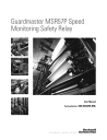
Cascaded Configurations
Only the middle or last relays in a multi-axis system can be configured for slave modes. Use the P20 [Cascaded Config] parameter to define the relay’s position in the system as Single Unit (Single), Cascaded
First Unit (Multi First), Cascaded Middle Unit (Multi Mid), or Cascaded
Last Unit (Multi Last).
For cascaded speed monitoring safety relays, connect the safety switches to the safety inputs (SS_In, SLS_In, DM_In, ESM_In, and
LM_In) of the first (master) axis only. Each feedback and the Motion
Power output (MP_Out) for Safe Stop functions are connected to their respective axis. The inputs are cascaded from one relay to the next by connecting the outputs from the previous relay to the inputs of the next relay.
125 Publication 440R-UM004A-EN-P - December 2008
125
Chapter 8 Slave Modes for Multi-axis Cascaded Systems
33
21
11
34
22
12
51
41
A1
52
42
A2
Door Monitor Input
Lock Monitor Input
24V DC
TLS3-GD2
440G-T27260
Power to
Release
Safe Stop Input
Safe Limited Speed Input
Enabling Switch Monitor Input
Manual Reset
24V DC Com
First Axis
Feedback
Cascaded Connections
First Unit (Multi-First)
Master
Axis 1
S12 SS_In_0
S22 SS_In_1
SS_Out_0 34
SS_Out_1 44
S52 SLS_In_0
S62 SLS_In_1
S72 ESM_In_0
S82 ESM_In_1
S11 Pulse_Source_0
S21 Pulse_Source_1
SLS_Out_0 68
SLS_Out_1 78
Middle Unit (Multi-Mid)
Slave
Axis 2
S12 SS_In_0
S22 SS_In_1
SS_Out_0 34
SS_Out_1 44
S52 SLS_In_0
S62 SLS_In_1
SLS_Out_0 68
SLS_Out_1 78
S32 DM_In_0
S42 DM_In_1
X32 LM_In_0
X42 LM_In_1
DC_Out_0 51
DC_Out_1 52
S32 DM_In_0
S42 DM_In_1
S34 Reset_In
Feedback A2
MP_Out_0 14
MP_Out_1 24
Auto
Reset
S34 Reset_In
Feedback
Second Axis
Feedback
DC_Out_0 51
DC_Out_1 52
Last Unit (Multi-Last)
Slave
Axis 3
S12 SS_In_0
S22 SS_In_1
SS_Out_0 34
SS_Out_1 44
S52 SLS_In_0
S62 SLS_In_1
SLS_Out_0 68
SLS_Out_1 78
S32 DM_In_0
S42 DM_In_1
A2
MP_Out_0 14
MP_Out_1 24
Auto
Reset
S34 Reset_In
Feedback
Third Axis
Feedback
DC_Out_0 51
DC_Out_1 52
To Door
Solenoid
MP_Out_0 14
MP_Out_1 24
A2
The inputs from the safety switches are monitored by the first relay, which is the master. A Safe Limited Speed Reset detected by the first relay is cascaded to the subsequent relays via the SLS_Out to SLS_In chain. Although all MSR57P units can be configured for any reset type, we recommend using automatic reset in all slave units to follow the master units reset type.
Any fault or transition of the SS_In input to OFF is detected by the first relay and initiates the configured Safe Stop Type to all of the relays via the SS_Out to SS_In chain.
Any fault in a slave relay only initiates the configured Safe Stop Type to that relay and to slave relays further down the chain.
IMPORTANT
Safe Stop monitoring is not initiated for non-faulted relays earlier in the cascaded chain.
IMPORTANT
The safety reaction time for a cascaded system includes the sum of the reaction times of each relay in the chain.
126
Publication 440R-UM004A-EN-P - December 2008
advertisement
* Your assessment is very important for improving the workof artificial intelligence, which forms the content of this project
Related manuals
advertisement