advertisement

1-9 System Set-up
1-9-1 Connection of a
Probe to the
System
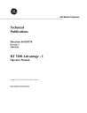
Illustration 1-7
Probe Connection
2
1
CAUTION
1-12
INTRODUCTION
1.
Insert a RT 3200 Advantage - I probe into the Probe 1 or Probe 2 connectors located on the panel below the keyboard. (See Illustration
2.
Lock the probe to the system connector by turning the knob clockwise.
Make sure that the name of the probe is right side up.
46-030370 REV 0
1-9-2 Probe Storage &
Cable Arm
Support
Illustration 1-8
Probe Storage
Cable arm
Probe holder
CAUTION
46-030370 REV 0
1.
Place the probe element assembly in the probe holder, as shown in
2.
Drape the probe cable on to the cable arm support also shown in
The probe element face is fragile. Mechanical shock could destroy individual probe elements.
INTRODUCTION 1-13
1-9-3 Power-up
Turn on system power by pressing the power switch to the "I" (ON) position.
1.
After the power switch is turned on, the system will beep twice.
2.
The LEDs on the front panel will flash on and the system performs its initialization routine.
3.
A few seconds later, the single B-Mode display format will appear on the monitor. The initial parameters at power up are shown in Table 1-1.
NOTE: Ideally, the unit needs to warm up for 30 minutes before it is ready and stabilized.
Table 1-1
Initial Parameter Selections
Initial Parameter Selections
MODE B (LED ON)
FUNCTION SELECTIONS OFF
FOCUS
SCALE
GAIN
DYNAMIC RANGE
MAP
IMAGE INVERSE
IMAGE REVERSE
Values depend on B-Mode parameter
presets programmed for the probe
selected.
1-14
INTRODUCTION 46-030370 REV 0
1-9-4 Adjustment of
Monitor Contrast and Brightness
Adjust the brightness and contrast of the display to the room lighting by using the controls under the left, front corner of the monitor (see Illustration 1-9).
1.
This control adjusts the brightness. The brightness will increase as the control is turned counterclockwise.
2.
This control adjusts contrast. The picture will become lighter as the control is turned counterclockwise.
Illustration 1-9
Monitor Display Adjustment
1 2
46-030370 REV 0 INTRODUCTION 1-15
1-9-5 Monitor Height
Adjustment
Always lower the monitor as much as possible before moving the unit.
1-16
INTRODUCTION 46-030370 REV 0
Illustration 1-10
Monitor Height Adjustment
Adjustment Button
1-9-5 Monitor Height
Adjustment
(continued)
To adjust the height of the display monitor, depress and hold down the adjustment button.
While depressing the button, firmly raise or lower the display monitor to the desired height.
Release the adjustment button to lock the monitor to the desired height.
46-030370 REV 0 INTRODUCTION 1-17
a a a a a a a a a
1-9-6 Foot Switch
Connection
Illustration 1-11
Foot Switch Connection
RS-232C Ext TV
In
1-18
INTRODUCTION
aaa a a
aa
A remote freeze foot switch is provided as standard equipment.
aaaa
The foot switch is connected to the lower accessory panel as shown in
Illustration 1-11.
The foot switch can be placed close to your work in order to quickly and conveniently capture the images necessary for measurement and recording.
Ext TV
Out In Out
FREEZE
Camera &
TV Printer
Video Out
Shutter
12Vdc for Camera
Caution
See Operating Manual
for connection.
Foot Switch aaa a a aa
aa
aa a a aa a aa
aaaaa aa aa aaa
a
46-030370 REV 0
a
SECTION 2
FRONT PANEL KEYBOARD
46-030370 REV 0 FRONT PANEL KEYBOARD 2-1
This page intentionally left blank.
2-2
FRONT PANEL KEYBOARD 46-030370 REV 0
advertisement
Related manuals
advertisement