advertisement

7
7 Service Activities
7 Service Activities
7-1 INSTALLATION CHECK LIST
EGX-600/400 INSTALLATION CHECK LIST
Model
EGX-600/400
Serial No.
User Name Date
Minimum Space Required
EGX-600 EGX-400
995mm(W) X 820mm(L) X 521mm(H) 795mm(W) X 719mm(L) X 521mm(H)
Classification
Purcahse Loan Unit Demo Unit Replacement
Unpacking Take the unit out of the carton box.
Accesorry box
94
7 Service Activities
Accessories
Follow the steps in "Unpacking and Repacking" on the packing carton to take out the included items and accessories. Before you attempt installation, make sure all the included items are present.
Operation panel : 1
Operation-panel connector cable : 1
Power cord : 1
Depth regulator nose unit : 1
Solid collet : 1 (*1) Clamps : 4 (*2)
Wrenches
(17 mm : 1, 10 mm : 1)
Hexagonal screw driver (2 mm) : 1
Hexagonal wrench
(3 mm) : 1
7
Remove the retainers.
Roland Software Package
CD-ROM : 1
User's Manual : 1
*1 This is for diameter 4.36 mm character cutters and flat cutters. It cannot be used with diamond scrapers or end mills.
*2 The bolts and nuts are installed on the machine. (They are used for attaching the packing retainers.)
1. Use the included wrench (10mm) and hexagonal wrench (3mm) to remove the retainers on the side of the unit. Then, lower the unit from the base.
95
7 Service Activities
2. Remove the four nuts and the retainer shown in the figure.
3. Loosen the three screws shown in the figure and remove the guide temporarily
7
4. Slide the bolts left on the table in step 2 to detach them.
5. Mount the guide at its original location.
6. Use the included hexagonal wrench (3mm) to remove the retainers for the spindle head. Then secure the screw on the left side of the head at its original location.
96
EGX-600/400
User
Explanation
Operation
7 Service Activities
Emergency Stop to Ensure Safety
The machine immediately stops operating and quits engraving by pressing the emergency stop switch.
Switching the Power On and Off
Moving the Spindle Head
The speed of movement is determined by how you press the movement buttons.
This machine has the function that moves the spindle head directly to the back-left position of the table (the VIEW position).
Starting and Stopping Spindle Rotation
To adjust the spindle rotating speed, you use the dial on the operation panel.
Menu Operations
Selecting the Cutter Installation Method
1. Character cutter , Flat cutter (with nose unit)
2. Character cutter , Flat cutter (without withoutse unit)
3. Diamond scraper (without withoutse unit)
4. End mill (without withoutse unit)
Loading Material and Setting the Reference Point for Cutting
1. Clamp
2. Adhesive sheet
3. Center vice
The reference point for engraving is the location where the X- and Y-axis coordinates are both (that is, the X- and Y-axis origin point).
Setting the Cutting Parameters
There are five kinds of settings and you can make the settings for these either on the machine by using the menus, or by using the program.
1. Spindle rotating speed
2. Feed rate in the X- and Y- axis directions
3. Feed rate in the Z-axis direction
4. Cutting depth (Z1)
5. Amount of cut-out during feed while raised (Z2)
Installation and Setup the Software
Coordinate Systems
Detailed Description of the Menus
7
EGX-600/400
User
Explanation
Maintenance
Daily Care
Clean the table, bed, the spindle head and the X-axis rail.
Maintenance and Inspection
Spindle Maintenance
Others Examples of Setting for Engraving Parameters
The Nose Unit
Optional Items
97
advertisement
* Your assessment is very important for improving the workof artificial intelligence, which forms the content of this project
Related manuals
advertisement
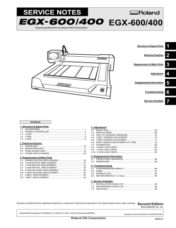
Table of contents
- 4 ACCESSORIES
- 5 FRAME & CONTROLLER
- 7 X AXIS
- 9 Y AXIS
- 11 Z AXIS
- 13 WIRING MAP
- 14 MAIN BOARD ASS’Y
- 22 PANEL BOARD ASS’Y
- 29 OTHER CIRCUIT BOARS
- 37 SPINDLE MOTOR_REPLACEMENT
- 40 X AXIS MOTOR_REPLACEMENT
- 44 Y AXIS MOTOR_REPLACEMENT
- 48 Z AXIS MOTOR_ REPLACEMENT
- 53 X AXIS LM GUIDE_REPLACEMENT
- 57 Y AXIS LM GUIDE_REPLACEMENT
- 62 X BELT_REPLACEMENT
- 67 Y BELT_REPLACEMENT
- 71 Special Tools
- 72 SERVICE MODE
- 75 HOW TO UPGRADE FIRMWARE
- 78 X BELT TENSION ADJUSTMENT
- 80 Y BELTTENSION ADJUSTMENT
- 82 RIGHT ANGLED ADJUSTMENT OF X RAIL
- 83 CALIBRATION
- 86 4-8 X AXIS LOAD CHECK
- 87 4-9 Y AXIS LOAD CHECK
- 88 4-10 Z AXIS LOAD CHECK
- 89 OPERATIONAL SEQUENCE
- 91 SENSOR MAP
- 92 POOR ENGRAVING RESULT
- 94 NOISE
- 95 SPINDLE LOCK
- 96 MOTOR ERROR (X, Y, Z Axis)
- 97 INSTALLATION CHECK LIST
- 101 MAINTENANCE CHECK LIST
- 102 Specification