- Computers & electronics
- Audio & home theatre
- Video switches
- Broadcast Tools
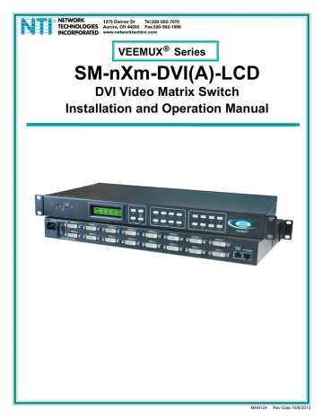
- VEEMUX SM-nXm-DVI-LCD
- Installation and Operation Manual
Enable Auto Status Mode. Network Technologies VEEMUX SM-nXm-DVIA-LCD, SS 4x4 Stereo Audio Matrix Switcher INC, VEEMUX SM-nXm-DVI-LCD
Add to my manuals
61 Pages
advertisement

NTI VEEMUX DVI VIDEO MATRIX SWITCH
SS_01- Enable Auto Status Mode
Command:
Byte 1 Byte 2 Byte 3 Byte 4 Byte 5 Byte 6
‘S’ ‘S’
(0x53)
Response:
(0x53)
Byte 1 Byte 2
Space
(0x20)
‘0’
(0x30)
‘1’
(0x31)
<CR>
(0x0D)
‘
∗’
<CR>
(0x2A) (0x0D)
Auto status mode is disabled by default whenever the connection is established, and this command must be entered to enable it.
When auto status mode is enabled, a message will be sent whenever an input/output connection changes from any source. The format of this message is given in the table below. The first two numeric digits are the output port number and the two after the colon are the number of the input port that is now connected to it.
Byte 1 Byte 2 Byte 3 Byte 4 Byte 5 Byte 6 Byte 7 Byte 8 Byte 9
‘p’
(0x70)
‘c’
(0x63)
Space
(0x20)
Output – 1st digit
(0x30 … 0x32)
Output – 2nd digit
(0x30 … 0x39)
‘:’
(0x3A)
Input – 1st digit
(0x30 … 0x32)
Input – 2nd digit
(0x30 … 0x39)
<CR>
(0x0D)
SS_00- Disable Auto Status Mode
Command:
Byte 1 Byte 2 Byte 3 Byte 4
‘S’ ‘S’
(0x53)
Response:
(0x53)
Space
(0x20)
‘0’
(0x30)
Byte 1 Byte 2
‘
∗’
<CR>
(0x2A) (0x0D)
This command disables auto status mode.
Byte 5
‘0’
(0x30)
Byte 6
<CR>
(0x0D)
SX- Examine connections
Command:
Byte 1 Byte 2 Byte 3
‘S’ ‘X’ <CR>
(0x53) (0x58) (0x0D)
Response:
Multiple lines, one line for each output:
Byte 1 Byte 2 Byte 3 Byte 4
‘p’
(0x70)
‘c’
(0x63)
Space
(0x20)
Byte 1 Byte 2 Byte 3
‘p’
(0x70)
Last line:
‘c’
(0x63)
Byte 1 Byte 2
‘
∗’
(0x2A)
<CR>
(0x0D)
Space
(0x20)
Byte 4
Byte 5
Output – 1st digit
(0x30 … 0x32)
Output – 2nd digit
(0x30 … 0x39)
Byte 5
Output – 1st digit
(0x30 … 0x32)
Output – 2nd digit
(0x30 … 0x39)
28
Byte 6
‘:’
(0x3A)
Byte 6
‘:’
(0x3A)
Byte 7
Input – 1st digit
(0x30 … 0x32)
Byte 8
Input – 2nd digit
(0x30 … 0x39)
Byte 7
Input – 1st digit
(0x30 … 0x32)
Byte 8
Input – 2nd digit
(0x30 … 0x39)
Byte 9
<CR>
(0x0D)
Byte 9
<CR>
(0x0D)
advertisement
* Your assessment is very important for improving the workof artificial intelligence, which forms the content of this project
Related manuals
advertisement
Table of contents
- 6 Introduction
- 6 Supported Web Browsers
- 7 Materials
- 8 Features and Functions
- 9 Installation
- 9 To Mount to a Rack
- 10 Make All Connections
- 13 Audio Connections
- 14 Operating the VEEMUX
- 14 Front Panel LCD with Keypad Control
- 15 LCD Menus
- 17 Save and Load (Recall) Config
- 18 USB Console Port
- 18 Installing Drivers
- 18 Windows XP-32 bit Installation
- 20 Windows 7-64 bit Installation
- 22 Using the USB Console Port
- 23 RS232 Control
- 23 Remote Connection
- 23 Baud Rate
- 23 Unit Address and Loop Back
- 25 Command Protocol
- 26 Autostatus
- 26 Matrix Switcher’s Control Program For Windows 9X, NT, 2000, XP, Vista and
- 27 SerTest- RS232 Interface Test Program
- 27 Main Options
- 27 Matrix Operations
- 27 Ethernet Operations
- 28 Setup Options
- 29 Ethernet Control
- 29 Telnet Interface-Port
- 31 Command Summary
- 32 Command Detail
- 32 Read Unit Size
- 32 Read Connection for Output Port
- 32 Connect Output Port to Input Port
- 32 Connect All Output Ports to Input Port
- 33 Enable Auto Status Mode
- 33 Disable Auto Status Mode
- 33 Examine connections
- 34 AO-Read Audio Connection for Output Port
- 34 AS-Connect Audio Output Port to Input Port
- 34 AA-Connect All Audio Outputs to Input Port
- 35 AV- Set Audio Volume for Output Port
- 35 AM- Mute/Unmute Audio Output Port
- 35 Terminate telnet session
- 36 Web Interface
- 36 Enter the Password
- 37 Main Menu
- 38 Video Switch Page
- 39 Administration
- 39 System Configuration
- 40 Network Configuration
- 41 Video Input Names
- 42 Video Output Names
- 43 Scanning Sequences
- 45 User Config