advertisement

-----> 1
Enter Current Date (mm/dd/yy) : 02/15/03 press the ENTER key to continue
-----------------------------------------------------------------------------
RTC configuration
-----------------------------------------------------------------------------
Select menu
1. Date(mm/dd/yy) : 02/15/03
2. Time(hh:mm:ss) : 13:27:20
<ESC> Back, <ENTER> Refresh
-----> 2
Enter Current Time (hh:mm:ss) : 13:25:00 press the ENTER key to continue
-----------------------------------------------------------------------------
RTC configuration
-----------------------------------------------------------------------------
Select menu
1. Date(mm/dd/yy) : 02/15/03
2. Time(hh:mm:ss) : 13:25:01
<ESC> Back, <ENTER> Refresh
----->
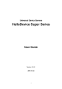
Figure A-11 RTC configuration within Bootloader Menu Program
A 5.4. Hardware Test Menu
Using the Hardware test menu, the user can test hardware components. There are three hardware test modes:
One time
Looping (without External test in Auto test)
Looping (with External test in Auto test)
If the user selects One time, an auto test or each component test is performed just once. In this mode, the ping test to the remote host (server IP address) and UART test are also performed once.
If the user selects Looping (without External test in Auto test), the auto test is performed repeatedly until the user presses the <ctrl-c> keys. In this mode, the ping test to the remote host (server IP address) and UART test are not performed.
Note: To perform the test on the Ethernet and UART properly, the user must connect an Ethernet cable to the Ethernet port of the Super Series and must plug the loopback connector to all the serial ports of the Super Series. There must exist a remote host with a valid IP address. The default server
IP address is 192.168.0.128 and it can be changed using the [Firmware Upgrade] menu. Otherwise, the test may not be performed properly.
-----------------------------------------------------------------------------
Hardware Test
-----------------------------------------------------------------------------
121
Select menu
0. Test Mode - One time
1. Auto test
2. DRAM test
3. FLASH test
4. LED test
5. EEPROM test
6. UART test
7. PC card test
8. Ethernet test
<ESC> Back, <ENTER> Refresh
-----> 0
-----------------------------------------------------------------------------
Hardware Test
-----------------------------------------------------------------------------
Select menu
0. Test Mode - Looping(without External test in Auto test)
1. Auto test
2. DRAM test
3. FLASH test
4. LED test
5. EEPROM test
6. UART test
7. PC card test
8. Ethernet test
<ESC> Back, <ENTER> Refresh
----->0
-----------------------------------------------------------------------------
Hardware Test
-----------------------------------------------------------------------------
Select menu
0. Test Mode - Looping(with External test in Auto test)
1. Auto test
2. DRAM test
3. FLASH test
4. LED test
5. EEPROM test
6. UART test
7. PC card test
8. Ethernet test
<ESC> Back, <ENTER> Refresh
----->0
-----------------------------------------------------------------------------
Hardware Test
-----------------------------------------------------------------------------
Select menu
0. Test Mode - One time
1. Auto test
2. DRAM test
3. FLASH test
4. LED test
5. EEPROM test
6. UART test
7. PC card test
8. Ethernet test
<ESC> Back, <ENTER> Refresh
----->
Figure A-12 Hardware test menu within Bootloader Menu Program
When the user selects [Auto test], a test of all the hardware components is performed automatically.
122
-----------------------------------------------------------------------------
Hardware Test
-----------------------------------------------------------------------------
Select menu
0. Test Mode - One time
1. Auto test
2. DRAM test
3. FLASH test
4. LED test
5. EEPROM test
6. UART test
7. PC card test
8. Ethernet test
<ESC> Back, <ENTER> Refresh
----->1
******* Hardware auto-detect and auto-test *******
[DRAM]
DRAM Test in progress ----------------------------------------[65536KB]
DRAM Test ----------------------------------------------------[SUCCESS]
[FLASH]
Flash Test Status---------------------------------------------[ 100 %]
Flash Test ---------------------------------------------------[SUCCESS]
[FAN]
Fan Status --------------------------------------------------[7020 RPM]
[LED]
SERIAL READY LED ON/OFF---------------------------------------3 time(s)
[EEPROM]
EEPROM : A Type exist
EEPROM Test ------------------------------------------------- [SUCCESS]
[UART]
<--Internal loop test-->
Port # 1 test in progressing(Read/Write)----------[SUCCESS]
Port # 2 test in progressing(Read/Write)----------[SUCCESS]
.
.
.
Port # 7 test in progressing(Read/Write)----------[SUCCESS]
Port # 8 test in progressing(Read/Write)----------[SUCCESS]
<--External loop test-->
Port # 1 test in progressing(Read/Write)----------[SUCCESS]
(RTS/CTS)-------------[SUCCESS]
(DTR/DSR)-------------[SUCCESS]
Port # 2 test in progressing(Read/Write)----------[SUCCESS]
(RTS/CTS)-------------[SUCCESS]
(DTR/DSR)-------------[SUCCESS]
.
.
.
Port # 7 test in progressing(Read/Write)----------[SUCCESS]
(RTS/CTS)-------------[SUCCESS]
(DTR/DSR)-------------[SUCCESS]
Port # 8 test in progressing(Read/Write)----------[SUCCESS]
(RTS/CTS)-------------[SUCCESS]
(DTR/DSR)-------------[SUCCESS]
[PCMCIA]
5V CARD
5.0V card found: Lucent Technologies WaveLAN/IEEE Version 01.01
123
Network Adapter Card
[Ethernet]
Ethernet chip test--------------------------------------------[SUCCESS]
PING 192.168.0.135 from 192.168.161.5 : 64 bytes of ethernet packet.
64 bytes from 192.168.0.135 : seq=0 ttl=255 timestamp=11172879 (ms)
64 bytes from 192.168.0.135 : seq=1 ttl=255 timestamp=11173874 (ms)
64 bytes from 192.168.0.135 : seq=2 ttl=255 timestamp=11174875 (ms)
64 bytes from 192.168.0.135 : seq=3 ttl=255 timestamp=11175876 (ms)
******* Hardware auto-detect and auto-test SUMMARY *******
1. DRAM Test -----------------------------------------------[SUCCESS]
2. FLASH Test -----------------------------------------------[SUCCESS]
3. FAN Test -----------------------------------------------[SUCCESS]
4. EEPROM Test-----------------------------------------------[SUCCESS]
5. UART Test Summary
Port NO | exist status | exist status | exist status | exist status
-----------------------------------------------------------------------------
--
Port 01-04| YES SUCCESS | YES SUCCESS | YES SUCCESS | YES SUCCESS
Port 05-08| YES SUCCESS | YES SUCCESS | YES SUCCESS | YES SUCCESS
6.PC CARD Test Summary
5V CARD
5.0V card found: Lucent Technologies WaveLAN/IEEE Version 01.01
Network Adapter Card
7. PING Test -----------------------------------------------[SUCCESS]
PRESS any key to continue!!
Figure A-13 Hardware test screen within Bootloader Menu Program
For each hardware component test, the user can skip a test by pressing the <ESC> key.
-------------------------------------------------------------------------------
Hardware Test
-------------------------------------------------------------------------------
Select menu
0. Test Mode - One time
1. Auto test
2. DRAM test
3. FLASH test
4. LED test
5. EEPROM test
6. UART test
7. PC card test
8. Ethernet test
<ESC> Back, <ENTER> Refresh
-----> 1
******* Hardware auto-detect and auto-test *******
[DRAM]
DRAM Test in progress ----------------------------------------[ 640KB]
DRAM Test ----------------------------------------------------[SKIPPED]
[FLASH]
Flash Test Status---------------------------------------------[ 2 %]
FLASH Test ---------------------------------------------------[SKIPPED]
Figure A-14 Skip the specific test using ESC key
If a failure occurs while Auto Test with looping mode is being performed, the test will stop and the
124
advertisement
* Your assessment is very important for improving the workof artificial intelligence, which forms the content of this project
Related manuals
advertisement