- No category
advertisement
5.2.2 How to Set Up your Computer’s IP Address for a Direct Connection
When your computer is connected directly to the OP6800 via an Ethernet connection, you need to assign an IP address to your computer. To assign the PC the address 10.1.1.1 with the subnetmask 255.255.255.248 under Windows 98, do the following.
Click on
Start > Settings > Control Panel
to bring up the Control Panel, and then double-click the Network icon. Depending on which version of Windows you are using, look for the
TCP/IP Protocol/Network > Dial-Up Connections/Network
line or tab.
Double-click on this line or select
Properties
or
Local Area Connections > Properties
to bring up the TCP/IP properties dialog box. You can edit the IP address and the subnet mask directly. (Disable “obtain an IP address automatically”.) You may want to write down the existing values in case you have to restore them later. It is not necessary to edit the gateway address since the gateway is not used with direct connect.
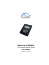
IP 10.1.1.1
Subnet mask
255.255.255.248
OP6800
Board
User’s PC
Ethernet crossover cable
#define MY_IP_ADDRESS "10.1.1.2"
#define MY_NETMASK "255.255.255.248"
Direct Connection PC to OP6800
38
MiniCom (OP6800)
advertisement
* Your assessment is very important for improving the workof artificial intelligence, which forms the content of this project
Related manuals
advertisement
Table of contents
- 5 1.1 Description
- 5 1.2 Features
- 6 1.3 Development and Evaluation Tools
- 6 1.3.1 Tool Kit
- 7 1.3.2 Software
- 8 1.4 CE Compliance
- 9 1.4.1 Design Guidelines
- 9 1.4.2 Interfacing the OP6800 to Other Devices
- 11 2.1 Connections
- 14 2.2 Demonstration Program on Power-Up
- 14 2.3 Display Contrast Adjustment
- 15 2.4 Programming Cable Connections
- 16 2.5 Installing Dynamic C
- 16 2.6 Starting Dynamic C
- 17 2.7 PONG.C
- 17 2.8 Where Do I Go From Here?
- 20 3.1 Pinouts
- 21 3.2 Digital I/O
- 21 3.2.1 Digital Inputs
- 22 3.2.2 Digital Outputs
- 23 3.3 Serial Communication
- 23 3.3.1 RS
- 23 3.3.2 RS
- 25 3.3.3 Programming Port
- 26 3.3.4 Ethernet Port (OP6800 models only)
- 27 3.4 Memory
- 27 3.4.1 SRAM
- 27 3.4.2 Flash Memory
- 28 3.5 Keypad Labeling
- 32 4.1 Programming Cable
- 32 4.1.1 Switching Between Program Mode and Run Mode
- 32 4.1.2 Detailed Instructions: Changing from Program Mode to Run Mode
- 32 4.1.3 Detailed Instructions: Changing from Run Mode to Program Mode
- 33 4.2 OP6800 Libraries
- 34 4.3 Sample Programs
- 34 4.3.1 Board ID
- 34 4.3.2 Demonstration Board
- 35 4.3.3 Digital I/O
- 35 4.3.4 Serial Communication
- 35 4.3.5 LCD/Keypad Module Sample Programs
- 36 4.3.6 TCP/IP Sample Programs
- 37 4.4 Font and Bitmap Converter
- 39 5.1 TCP/IP Connections
- 41 5.2 TCP/IP Sample Programs
- 41 5.2.1 How to Set IP Addresses in the Sample Programs
- 42 5.2.2 How to Set Up your Computer’s IP Address for a Direct Connection
- 43 5.2.3 Run the PINGME.C Demo
- 43 5.2.4 Running More Demo Programs With a Direct Connection
- 44 5.2.5 LCD/Keypad Sample Programs Showing TCP/IP Features
- 45 5.3 Where Do I Go From Here?
- 47 6.1 Installation Guidelines
- 48 6.2 Mounting Instructions
- 48 6.2.1 Bezel-Mount Installation
- 52 A.1 Electrical and Mechanical Specifications
- 55 A.2 Conformal Coating
- 56 A.3 Jumper Configurations
- 57 A.4 Use of Rabbit 2000 Parallel Ports
- 59 A.5 I/O Address Assignments
- 61 B.1 Power Supplies
- 62 B.2 Batteries and External Battery Connections
- 62 B.2.1 Battery-Backup Circuit
- 63 B.2.2 Power to VRAM Switch
- 63 B.2.3 Reset Generator
- 64 B.3 Chip Select Circuit
- 66 C.1 Mechanical Dimensions and Layout
- 67 C.2 Power Supply
- 69 C.3 Using the Demonstration Board
- 74 D.1 Board Initialization (OP68xx.LIB)
- 75 D.2 Digital I/O (OP68xx.LIB)
- 76 D.3 Serial Communication (OP68xx.LIB)
- 78 D.4 LEDs (OP68xx.LIB)
- 79 D.5 LCD Display
- 96 D.6 Keypad