advertisement

Device Configuration
LAG Configuration - Advanced Tab
To view the Advanced tab of the LAG Configuration dialog box for a selected LAG:
1. Click the LAG’s symbol in the Tree View.
Or
Click the LAG’s icon in the Chassis View. The LAG Configuration dialog box opens to the General tab.
2. Click
Advanced
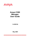
. The Advanced tab of the LAG Configuration dialog box appears.
Figure 10. LAG Configuration Dialog Box - Advanced Tab
Avaya C360 Manager User Guide 45
Chapter 3
The following table provides a list of the fields in the Advanced tab of the
LAG Configuration dialog box and their descriptions:
Table 13. LAG Configuration Fields - Advanced Tab
Field
Flow Control
Advertisement
LAG STP Mode
Description
The flow control values advertised by the
LAGs on the selected LAG. These values limit the flow control possibilities to be decided by
Auto-Negotiation.
Enables LAG Spanning Tree. The Spanning
Tree mode creates a logical tree topology out of any arrangement of bridges, resulting in a single path between any two end stations. The
Spanning Tree Mode also provides high fault tolerance. The possible states are:
•
Enable
- Enables the Spanning Tree
Mode.
•
Disable
- Disables the Spanning Tree
Mode.
For more information refer to Spanning Tree
Algorithm (STA) in The Reference Guide.
LAG STP State
STP Admin Edge
The state of the LAG in terms of the Spanning
Tree Protocol. The possible states are:
• Disable - The LAG is disabled.
• Blocking - STP is enabled and currently blocking the LAG. The LAG is effectively disabled to prevent the formation of a loop in the network.
• Forwarding - The LAG is currently forwarding information received.
The administrative state of the edge LAG parameter. Possible states include:
• TRUE - This LAG is assumed to be an edge LAG.
• FALSE - This LAG is assumed not to be an edge-LAG.
46 Avaya C360 Manager User Guide
Device Configuration
Table 13. LAG Configuration Fields - Advanced Tab (Continued)
Field
STP Oper Edge
STP Admin P2P
STP Oper P2P
STP Admin Path Cost
Description
The operational state of the edge LAG parameter.
• TRUE - This LAG is operating in the state specified in STP Admin Edge.
• FALSE - A BPDU was received by the
LAG.
The administrative point-to-point status of the
LAN segment attached to this LAG. Possible statuses include:
• True - The LAG should always be treated as if it is connected to a point-to-point link.
• forceFalse - The LAG should be treated as having a shared media connection.
• auto - The LAG is considered to have a point-to-point link if it is an Aggregator and all of its members are aggregative, or if the MAC entity is configured for full duplex operation, either through auto-negotiation or by management means.
The operational point-to-point status of the
LAN segment attached to this LAG. It indicates whether a LAG is considered to have a point-to-point connection or not.
The value is determined by STP Admin P2P.
The administratively assigned value for the contribution of this LAG to the path cost of paths towards the spanning tree root. A value of 0 assigns the automatically calculated default Path Cost value to the LAG.
STP Admin Path Cost complements STP Path
Cost, which returns the operational value of the path cost.
STP Path Cost
The operational cost factor used by Spanning
Tree Algorithm to determine the most efficient route for forwarding traffic to its destination while removing loops in the network.
For more information refer to Spanning Tree
Algorithm (STA) in The Reference Guide.
Avaya C360 Manager User Guide 47
Chapter 3
Table 13. LAG Configuration Fields - Advanced Tab (Continued)
Field Description
STP Force Migration
Port Classification
When checked and in RSTP mode, the LAG is forced to transmit RSTP BPDUs.
The classification of a specific LAG. Port
Classification allows network managers to specify each LAG level’s importance. The possible states are:
•
Regular
- Normal users.
•
Valuable
- Servers or critical users.
For more information refer to Port
Classificationin The Reference Guide.
For more information on the user interface, refer to
“Using Dialog Boxes and Tables” on page 28
.
Viewing Port Configuration
The Port Configuration dialog box contains tabs that provide you with information specific to a selected port.
The General tab of the Port Configuration dialog box provides detailed information about the port, such as the port name, type, functionality, status, VLAN ID, mode of operation, and any faults occurring on the port.
The Advanced tab of the Port Configuration dialog box provides detailed information about the port’s STP configuration and port classification.
The 802.1x tab of the Port Configuration dialog box provides detailed information about the port’s 802.1x configuration. For more information about 802.1x security, refer to
The Power tab of the Port Configuration dialog box provides information about the port’s PoE configuration. For more information about PoE, refer to
Chapter 4, Power Over Ethernet .
The Get/Set Toolbar provides an alternative, quick method to view and change the port’s configuration. For more information on the Get/Set
Toolbar, refer to “Get/Set Toolbar” on page 21 .
* Note: The configuration of ports that participate in a LAG cannot be changed using the Port Configuration dialog box. Use the LAG
Configuration dialog box instead.
48 Avaya C360 Manager User Guide
advertisement
* Your assessment is very important for improving the workof artificial intelligence, which forms the content of this project
Related manuals
advertisement