advertisement
Chapter 20
VRRP Table
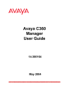
To define and display the VRRP table, select
IP Route > VRRP >
VRRP Table
. The VRRP table opens.
Figure 101. VRRP Table
248
The following parameters are displayed:
Field
VLAN Name
(not for X330WAN)
L2 Interface Name
(X330WAN router only)
VRID
Table 72. VRRP Table Parameters
Description
The name of the selected interface.
IP Address
A number which, along with an interface index
(ifIndex), serves to uniquely identify a virtual router on a given VRRP router. A set of one or more associated addresses is assigned to a VRID.
The IP address associated with this virtual router.
If more than one IP address is associated with this virtual router,
Click for Details
appears in the
IP Address
field. Clicking the field opens the Form View showing all IP addresses associated with this virtual router.
The IP addresses must be on a local subnet on the VLAN.
Avaya C360 Manager User Guide
IP Route
Field
State
Master IP Address
Priority
Table 72. VRRP Table Parameters (Continued)
Virtual Route Up
Time
Description
The state of the virtual router. Possible states are:
•
initialize
- The virtual router is not functional.
•
backup
- The virtual router is monitoring the availability of the master router.
•
master
- The virtual router is forwarding packets with IP addresses associated with this virtual router.
The IP address of the physical router currently acting as the Virtual Router’s Master Router.
This object specifies the priority to be used for the virtual router master election process.
Higher values imply higher priority.
A priority of '0', although not settable, is sent by the master router to indicate that this router has ceased to participate in VRRP and a backup virtual router should transition to become a new master.
A priority of 255 is used for the router that owns the associated IP address(es).
The time when the virtual router’s state changed from initialized to backup
or master
.
The time is expressed in ticks (1/60 of a second).
Advertise Interval
MAC Address
Primary IP Address
Preempt Mode
The interval, in seconds, between VRRP advertisement messages sent by the master router.
The virtual MAC address of the virtual router.
The physical router’s IP address to be used if it is elected to be Master Router. The Primary IP
Address must belong to the physical router and be on the selected VLAN.
If this parameter is set to 0.0.0.0, the IP address which is numerically lowest will be selected.
If checked, the virtual router with the highest priority will preempt active routers and become the master router.
Avaya C360 Manager User Guide 249
Chapter 20
Field
Auth Type
Table 72. VRRP Table Parameters (Continued)
Description
Auth Key
Authentication Type. Possible methods are:
• None
• Simple
The password for this interface. This is only used if the
Auth Type
is set to
Simple
. The password may contain up to 8 characters. It may be configured here, but not viewed.
To associate IP addresses with a selected virtual router:
1. Select a virtual router in the VRRP table.
2. Ensure that the Form View is visible.
3. Enter the IP address to associate with the selected router in the textbox under the
IP Addresses
listbox in the Form View.
4. Click . The IP address is associated with the virtual router.
To disassociate IP addresses from a selected virtual router:
1. Select a virtual router in the VRRP table.
2. Ensure that the Form View is visible.
3. Select the IP address from the
IP Addresses
listbox in the Form
View.
4. Click router.
. The IP address is no longer associated with the virtual
You can modify VRRP parameters. For more information on editing tables, refer to
“Editing Tables” on page 211 .
250 Avaya C360 Manager User Guide
advertisement
* Your assessment is very important for improving the workof artificial intelligence, which forms the content of this project
Related manuals
advertisement
Table of contents
- 14 Avaya C360 Manager as Part of Avaya Integrated Management
- 14 Running Avaya C360 Manager from Avaya Network Management Console
- 14 Running Avaya C360 Manager from HP NNM
- 15 Avaya C360 Manager via Web Management
- 16 Application Tabs
- 17 Status Line
- 20 Application Toolbar
- 21 Get/Set Toolbar
- 23 Tree View
- 23 Desktop
- 24 Chassis View
- 25 GBIC Ports
- 26 Selecting Elements
- 27 Dialog Area
- 29 Opening the Help to the Contents Page
- 29 Opening the Help to a Topic of Interest
- 32 Device Information - General Tab
- 33 Device Information - Advanced Tab
- 37 Module Configuration - General Tab
- 39 Module Configuration - Advanced Tab
- 42 LAG Configuration - General Tab
- 45 LAG Configuration - Advanced Tab
- 49 Port Configuration - General Tab
- 53 Port Configuration - Advanced Tab
- 60 Viewing PoE Port Information
- 60 Viewing PoE Configuration
- 61 PoE Module Configuration
- 62 PoE Port Configuration
- 66 Viewing Module Configuration
- 66 Switch Config
- 67 MG Config
- 68 MGP Config
- 72 MGC Config
- 74 Viewing Media Module Configuration
- 78 VoIP Resources
- 82 VoIP Config
- 83 VoIP Status
- 90 Channel Group - PPP Session Information
- 91 Channel Group
- 93 Advanced
- 94 PPP
- 96 Channel Group - Frame Relay Information
- 97 Frame Relay
- 100 Sub- Interfaces
- 102 DLCIs
- 105 Viewing the Channel Groups Table
- 107 Creating, Editing, and Deleting Channel Groups
- 107 The Channel Group Wizard
- 108 Welcome Screen
- 108 Select Name and Encapsulatio n Screen
- 109 Select E1/T1 Port Screen
- 110 Select Channels and Speed Screen
- 111 Confirmation Screen
- 112 USP - PPP Interface
- 112 Serial Port
- 114 Advanced
- 117 PPP
- 119 USP - Frame Relay Interface
- 119 Frame Relay
- 122 Sub- Interfaces
- 125 DLCIs
- 128 Viewing the Backup Interfaces Table
- 129 The Backup Interface Wizard
- 130 Welcome Screen
- 131 Select Module Screen
- 132 Select Primary Interface Screen
- 133 Select Backup Interface Screen
- 134 Backup Interface Parameters Screen
- 135 Confirmation Screen
- 138 The Pie Chart
- 138 The Traffic Graph
- 139 Viewing Traffic Statistics
- 139 Zooming In and Out of the Graph
- 139 Scrolling within the Graph
- 139 Unfreezing the Graph
- 139 Traffic Types
- 142 VLANs Overview
- 142 Master VLAN List
- 142 VLAN Tags
- 144 VLAN Tree
- 145 Selection List
- 146 Port Configuration Area
- 148 Creating VLANs
- 149 Renaming VLANs
- 150 Synchronizing VLAN Names
- 151 Deleting VLANs
- 151 Selecting Ports
- 152 Viewing Port VLAN Settings
- 152 Using the Port Configuration Area
- 153 Drag-and-Drop
- 158 Welcome Screen
- 159 Base Port Selection Screen
- 160 Member Port Selection Screen
- 161 LAG Name Screen
- 162 Confirmation Screen
- 170 Welcome Screen
- 171 Primary Port Selection Screen
- 172 Secondary Port Selection Screen
- 173 Name and Type Screen
- 174 Confirmation Screen
- 179 Create Welcome Screen
- 180 Edit/Delete Welcome Screen
- 181 Source Port Selection Screen
- 182 Destination Port Selection Screen
- 183 Frames Direction Selection Screen
- 184 Confirmation Screen
- 196 Adding and Removing Managers
- 196 Editing Trap Reporting Statuses
- 199 Sorting the List of Stations
- 201 802.1x Port Security Overview
- 202 Configuring 802.1x Port Security
- 206 Router
- 206 Layer 2 Switch
- 208 Toolbar
- 209 Tree View
- 210 Table Area
- 210 Form Area
- 211 Creating New Table Entries
- 211 Modifying Table Entries
- 211 Deleting Table Entries
- 212 Running Changes
- 212 Committed Changes
- 213 Opening the Help to the Contents Page
- 213 Opening the Help to a Topic of Interest
- 229 DHCP/BOOTP Global Parameter
- 230 DHCP/BOOTP Parameters
- 232 RIP Global Parameters
- 234 RIP Interfaces
- 237 OSPF Global Parameters
- 239 OSPF Interfaces
- 241 OSPF Area Parameters
- 242 OSPF Link State Database
- 244 OSPF External Database
- 245 OSPF Neighbors
- 247 VRRP Global Parameters
- 248 VRRP Table
- 251 CRTP Interfaces
- 254 File Menu
- 254 View Menu
- 254 Configure Menu
- 256 Actions Menu
- 256 Tools Menu
- 257 Help Menu
- 257 File Menu
- 257 Edit Menu
- 258 View Menu
- 258 Action Menu
- 258 Help Menu