advertisement

System Event Log Troubleshooting Guide for Intel
®
Memory Subsystem
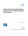
Byte Field
13 Event Direction and
Event Type
14 Event Data 1
15 Event Data 2
16 Event Data 3
Description
[7] Event direction
0b = Assertion Event
1b = Deassertion Event
[6:0] Event Type = 09h (digital Discrete)
[7:6] – 10b = OEM code in Event Data 2
[5:4] – 00b = Unspecified Event Data 3
[3:0] – Event Trigger Offset as described in Table 53
Not used
Not used
Table 53: Mirroring Configuration Status Sensor Event Trigger Offset – Next Steps
Hex
Event Trigger Offset
Description
01h The system has been configured into
Mirrored Channel RAS Mode.
00h The system has been configured out of Mirrored Channel RAS Mode.
Description
User enabled mirrored channel mode in setup.
Mirrored channel mode is disabled (either in setup or due to unavailability of memory at post, in which case post error
8500 is also logged).
7.1.2 Mirrored Redundancy State Sensor
Informational event only.
Next Steps
1. If this event is accompanied by a post error 8500, there was a problem applying the mirroring configuration to the memory. Check for other errors related to the memory and troubleshoot accordingly.
2. If there is no post error then mirror mode was simply disabled in BIOS setup and this should be considered informational only.
This sensor provides the RAS Redundancy state for the Memory Mirrored Channel Mode.
Revision 1.1 Intel order number G74211-002 47
Memory Subsystem
48
Byte
8
9
Field
Generator ID
11 Sensor Type
12 Sensor Number
13 Event Direction and
Event Type
14 Event Data 1
15 Event Data 2
Table 54: Mirrored Redundancy State Sensor Typical Characteristics
Description
0001h = BIOS POST
0ch = Memory
01h
[7] Event direction
0b = Assertion Event
1b = Deassertion Event
[6:0] Event Type = 0Bh (Generic Discrete)
[7:6] – 10b = OEM code in Event Data 2
[5:4] – 10b = OEM code in Event Data 3
[3:0] – Event Trigger Offset as described in Table 55
[7:4] – If Domain Instance Type (ED3) is set to Local, this field specifies the mirroring domain local sub-instances – which channels are included in this sub-instance:
0000b – Reserved
0001b – {Ch A, Ch B}
0010b – {Ch A, Ch C}
0011b – {Ch B, Ch C}
0100b-1110b – Reserved
If Domain Instance Type (ED3) is set to Global, this field specifies the 0-based Socket ID of the first participant processor in this mirroring domain global instance.
A value of 1111b indicates that this field is unused and does not contain valid data.
[3:0] – If Domain Instance Type (ED3) is set to Local, this field specifies the sparing domain local sub-instances – which channels are included in this sub-instance:
0000b – Reserved
0001b – {Ch A, Ch B, Ch C} (only configuration possible on Intel
®
Server Boards)
S5500/S5520
0010b-1110b – Reserved
If Domain Instance Type (ED3) is set to Global, this field specifies the 0-based Socket ID of the first participant processor in this sparing domain global instance.
A value of 1111b indicates that this field is unused and does not contain valid data.
Intel order number G74211-002 Revision 1.1
advertisement
* Your assessment is very important for improving the workof artificial intelligence, which forms the content of this project