advertisement

Part I, Chapter 2: Pin Description L-761e_2
2 Pin Description
Please note that all module connections are not to exceed their expressed maximum voltage or current.
Maximum signal input values are indicated in the corresponding controller manuals/datasheets. As damage from improper connections varies according to use and application, it is the user's responsibility to take appropriate safety measures to ensure that the module connections are protected from overloading through connected peripherals.
All controller signals extend to surface mount technology (SMT) connectors (0.635 mm) lining two sides of the module (referred to as the phyCORE-Connector). This allows the phyCORE-AM3517 to be plugged into any target application like a "big chip."
The numbering scheme for the phyCORE-Connector is based on a two dimensional matrix in which column positions are identified by a letter and row position by a number. Pin 1A, for example, is always located in the upper left hand corner of the matrix. The pin numbering values increase moving down on the board. Lettering of the pin connector rows progresses alphabetically from left to right (refer to
).
The numbered matrix can be aligned with the phyCORE-AM3517 (viewed from above; phyCORE-
Connector pointing down) or with the socket of the corresponding phyCORE Carrier Board/user target circuitry. The upper left-hand corner of the numbered matrix (pin 1A) is thus covered with the corner of the phyCORE-AM3517 marked with a number 1. The numbering scheme is always in relation to the PCB as viewed from above, even if all connector contacts extend to the bottom of the module.
The numbering scheme is thus consistent for both the module’s phyCORE-Connector as well as mating connectors on the phyCORE Carrier Board or target hardware, thereby considerably reducing the risk of pin identification errors.
Since the pins are exactly defined according to the numbered matrix previously described, the phyCORE-
Connector is usually assigned a single designator for its position (X2 for example). In this manner the phyCORE-Connector comprises a single, logical unit regardless of the fact that it could consist of more than one physical socketed connector. The location of row 1 on the board is marked by a number 1 on the
PCB to allow easy identification.
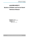
illustrates the numbered matrix system. It shows a phyCORE-AM3517 with SMT phyCORE-
Connectors on its underside (defined as dotted lines) mounted on a Carrier Board. In order to facilitate understanding of the pin assignment scheme, the diagram presents a cross-view of the phyCORE module showing these phyCORE-Connectors mounted on the underside of the module’s PCB.
© PHYTEC America LLC 2012 7
Part I, Chapter 2: Pin Description L-761e_2
Fig. 2-1. Pin-out of the phyCORE-Connector
(Top View, with Cross Section Insert)
9A
10A
11A
12A
13A
14A
15A
16A
5A
6A
7A
8A
1A
2A
3A
4A
17A
18A
19A
20A
21A
22A
Table 2-1. Pin Descriptions, phyCORE-Connector X2, Row A
Pin Signal
GPMC_NCS7
GND
GPMC_NCS3
GPMC_NCS2
GPMC_NCS1 xGPMC_NWE
GND
GPMC_NBE0_CLE
GPMC_NBE1
GPMC_WAIT0
GPMC_WAIT2
GND
GPMC_A9
GPMC_A8
GPMC_A7
GPMC_A4
GND
GPMC_A1
GPMC_D15
GPMC_D14
GPMC_D11
GND
I/O
Signal
Level
Description
O VDDSHV GPMC interface - control (active low chip select 7)
Ground
O VDDSHV GPMC interface - control (active low chip select 3)
O VDDSHV GPMC interface - control (active low chip select 2)
O VDDSHV GPMC interface - control (active low chip select 1)
O VDDSHV GPMC interface - control (active low write enable)
Ground
O VDDSHV GPMC interface - control (active low bus enable 0)
-
I
O VDDSHV GPMC interface - control (active low bus enable 1)
I VDDSHV GPMC interface - control (active low wait signal)
VDDSHV
-
GPMC interface - control (active low wait signal)
Ground
O VDDSHV GPMC interface - address
O VDDSHV GPMC interface - address
O VDDSHV GPMC interface - address
O VDDSHV GPMC interface - address
-
I
I
I
Ground
O VDDSHV GPMC interface - address
VDDSHV
VDDSHV
GPMC interface - data
GPMC interface - data
VDDSHV GPMC interface - data
Ground
© PHYTEC America LLC 2012 8
Part I, Chapter 2: Pin Description L-761e_2
Table 2-1. Pin Descriptions, phyCORE-Connector X2, Row A (Continued)
Pin
32A
33A
34A
35A
36A
37A
38A
39A
40A
41A
42A
43A
23A
24A
25A
26A
27A
28A
29A
30A
31A
44A
45A
46A
47A
48A
49A
50A
51A
52A
53A
54A
55A
56A
Signal
GPMC_D8
GPMC_D7
GPMC_D6
GPMC_D3
GND
GPMC_D0
CCDC_WEN
CCDC_VD
CCDC_FIELD
GND
CCDC_DATA5
CCDC_DATA4
CCDC_DATA3
CCDC_DATA0
GND
RMII_MDIO_CLK
RMII_MDIO_DATA
RMII_RXD1
RMII_RXER
GND
ETK_D15
ETK_D14
ETK_D13
ETK_D10
GND
HSUSB1_DATA3
HSUSB1_DATA6
HSUSB1_DATA5
HSUSB1_DATA2
GND
HSUSB1_STP xHSUSB1_CLK
MMC2_DAT7
MMC2_DAT4
I/O
Signal
Level
Description
I
I
I
I VDDSHV GPMC interface - data
VDDSHV GPMC interface - data
VDDSHV GPMC interface - data
VDDSHV GPMC interface - data
-
I
Ground
VDDSHV GPMC interface - data
I VDDSHV CCD Camera interface - control (write enable)
IO VDDSHV CCD Camera interface - control (vertical sync)
IO VDDSHV CCD Camera interface - control (field identification)
I
I
-
I
Ground
VDDSHV CCD Camera interface - data
VDDSHV CCD Camera interface - data
VDDSHV CCD Camera interface - data
-
I VDDSHV CCD Camera interface - data
Ground
O VDDSHV Ethernet - MDIO interface clock
IO VDDSHV Ethernet - MDIO interface data
I
I VDDSHV Ethernet MAC - RMII data RX data
VDDSHV Ethernet MAC - RMII data RX error
Ground
O VDDSHV ARM Embedded Toolkit debug interface (other signal on HSUSB interface)
O VDDSHV ARM Embedded Toolkit debug interface (other signal on HSUSB interface)
O VDDSHV ARM Embedded Toolkit debug interface (other signal on HSUSB interface)
O VDDSHV ARM Embedded Toolkit debug interface (other signal on HSUSB interface)
Ground
IO VDDSHV High Speed USB digital interface - data
IO VDDSHV High Speed USB digital interface - data
IO VDDSHV High Speed USB digital interface - data
IO VDDSHV High Speed USB digital interface - data
Ground
O VDDSHV High Speed USB digital interface - control
O VDDSHV High speed USB digital interface 1 - clock
IO VDDSHV MMC / SDIO 2 interface - data
IO VDDSHV MMC / SDIO 2 interface - data
© PHYTEC America LLC 2012 9
Part I, Chapter 2: Pin Description L-761e_2
Table 2-1. Pin Descriptions, phyCORE-Connector X2, Row A (Continued)
Pin
57A
58A
59A
60A
61A
62A
63A
64A
65A
75A
76A
77A
78A
79A
80A
66A
67A
68A
69A
70A
71A
72A
73A
74A
Signal
GND
MMC2_DAT1
MMC2_DAT0
MMC2_CMD
MCSPI2_CS1
GND
MCSPI2_CS0
MCSPI2_SIMO
MCSPI2_SOMI xMCSPI2_CLK
GND
TV_OUT1
TV_OUT2
MCBSP4_CLKX
MCBSP4_DR
GND
MCBSP4_DX
MCBSP4_FSX
N/C
JTAG_EMU0
GND
JTAG_NTRST
JTAG_TDI xJTAG_TDO
I/O
Signal
Level
Description
Ground
IO VDDSHV MMC / SDIO 2 interface - data
IO VDDSHV MMC / SDIO 2 interface - data
O VDDSHV MMC / SDIO 2 interface - command
O VDDSHV Multichannel Serial Peripheral Interface 2 - chip select 1
Ground
IO VDDSHV Multichannel Serial Peripheral Interface 2 - chip select 0
IO VDDSHV Multichannel Serial Peripheral Interface 2 - slave data in, master data out
IO VDDSHV Multichannel Serial Peripheral Interface 2 - slave data out, master data in
IO VDDSHV Multichannel Buffered Serial Port 2 - clock
Ground
O
O
Analog TV Out signal 1
Analog TV Out signal 2
IO VDDSHV Multichannel Buffered Serial Port 4 - TX clock
I VDDSHV Multichannel Buffered Serial Port 4 - data receive
Ground
IO VDDSHV Multichannel Buffered Serial Port 4 - data transmit
IO VDDSHV Multichannel Buffered Serial Port 4 - frame sync transmit
-
I
No connect
IO VDDSHV JTAG - test emulation
-
VDDSHV
Ground
JTAG - test reset
I VDDSHV JTAG - test data in
O VDDSHV JTAG - test data out
Table 2-2. Pin Descriptions, phyCORE-Connector X2, Row B
Pin
1B
2B
3B
4B
5B
Signal
GPMC_NCS6
GPMC_NCS5
GPMC_NCS4
GND
N/C
I/O
Signal
Level
Description
O VDDSHV GPMC interface - control
O VDDSHV GPMC interface - control
O VDDSHV GPMC interface - control
Ground
No connect
© PHYTEC America LLC 2012 10
Part I, Chapter 2: Pin Description L-761e_2
30B
31B
32B
33B
34B
35B
36B
37B
22B
23B
24B
25B
26B
27B
28B
29B
38B
39B
40B
41B
42B
43B
14B
15B
16B
17B
18B
19B
20B
21B
6B
7B
8B
9B
10B
11B
12B
13B
Table 2-2. Pin Descriptions, phyCORE-Connector X2, Row B (Continued)
Pin Signal I/O
Signal
Level
Description
GPMC_NWP
GPMC_NOE
O VDDSHV GPMC interface - control (active low write protect)
O VDDSHV GPMC interface - control (active low output enable) xGPMC_NADV_ALE O VDDSHV GPMC interface - control
GND Ground
GPMC_WAIT1
GPMC_WAIT3 xGPMC_CLK
GPMC_A10
I
I
O
O
VDDSHV
VDDSHV
VDDSHV
VDDSHV
GPMC interface - control (active low wait)
GPMC interface - control (active low wait)
GPMC interface - clock
GPMC interface - address
GND
GPMC_A6
GPMC_A5
GPMC_A3
GPMC_A2
GND
GPMC_D13
GPMC_D12
-
O VDDSHV GPMC interface - address
-
I
I
-
O VDDSHV GPMC interface - address
O VDDSHV GPMC interface - address
O VDDSHV GPMC interface - address
-
VDDSHV
VDDSHV
Ground
Ground
GPMC interface - data
GPMC interface - data
GPMC_D10
GPMC_D9
GND
GPMC_D5
GPMC_D4
GPMC_D2
GPMC_D1
GND
CCDC_PCLK
CCDC_HD
CCDC_DATA7
CCDC_DATA6
GND
CCDC_DATA2
CCDC_DATA1
RMII_50MHZ_CLK
RMII_CRS_DV
GND
RMII_RXD0
RMII_TXD1
RMII_TXD0
RMII_TXEN
-
I
-
I
I
-
I
I
I
I
I
-
I
I
I
I
I
O
VDDSHV GPMC interface - data
VDDSHV GPMC interface - data
Ground
VDDSHV GPMC interface - data
VDDSHV GPMC interface - data
VDDSHV GPMC interface - data
VDDSHV GPMC interface - data
Ground
IO VDDSHV CCD Camera interface - control (pixel clock)
IO VDDSHV CCD Camera interface - control (horizontal sync)
VDDSHV
VDDSHV
-
VDDSHV
VDDSHV
VDDSHV
VDDSHV
-
CCD Camera interface - data
CCD Camera interface - data
Ground
CCD Camera interface - data
CCD Camera interface - data
Ethernet MAC - RMII clock
Ethernet MAC - RMII data valid
Ground
VDDSHV Ethernet MAC - RMII data RX data
O VDDSHV Ethernet MAC - RMII data TX data
O VDDSHV
VDDSHV
Ethernet MAC - RMII data TX data
Ethernet MAC - RMII data TX enable
© PHYTEC America LLC 2012 11
Part I, Chapter 2: Pin Description L-761e_2
63B
64B
65B
66B
67B
68B
69B
70B
71B
72B
73B
55B
56B
57B
58B
59B
60B
61B
62B
47B
48B
49B
50B
51B
52B
53B
54B
HSUSB1_NXT
HSUSB1_DIR
GND
HSUSB1_DATA4
HSUSB1_DATA7
HSUSB1_DATA1
HSUSB1_DATA0
GND
MMC2_DAT6
MMC2_DAT5
MMC2_DAT3
MMC2_DAT2
GND xMMC2_CLK
I2C3_SCL
I2C3_SDA
UART1_RTS
GND
UART1_CTS
N/C
N/C
N/C
GND
MCBSP3_CLKX
MCBSP3_DR
MCBSP3_DX
MCBSP3_FSX
Table 2-2. Pin Descriptions, phyCORE-Connector X2, Row B (Continued)
Pin
44B
45B
46B
74B
75B
76B
77B
Signal
GND
ETK_D12
ETK_D11
GND
N/C
JTAG_EMU1 xJTAG_RTCK
I/O
Signal
Level
Description
Ground
O VDDSHV ARM Embedded Toolkit debug interface (other signal on HSUSB interface)
I
I
O VDDSHV ARM Embedded Toolkit debug interface (other signal on HSUSB interface)
VDDSHV
VDDSHV
High Speed USB digital interface - control
High Speed USB digital interface - control
Ground
IO VDDSHV High Speed USB digital interface - data
IO VDDSHV High Speed USB digital interface - data
IO VDDSHV High Speed USB digital interface - data
IO VDDSHV High Speed USB digital interface - data
Ground
IO VDDSHV MMC / SDIO 2 interface - data
IO VDDSHV MMC / SDIO 2 interface - data
IO VDDSHV MMC / SDIO 2 interface - data
IO VDDSHV MMC / SDIO 2 interface - data
Ground
O VDDSHV MMC / SDIO 2 interface - clock
O VDDSHV I²C bus 3 clock
IO VDDSHV I²C bus 3 data
O VDDSHV UART 1 ready to send
Ground
-
-
-
I VDDSHV UART 1 clear to send
No connect
-
-
No connect
No connect
Ground
IO VDDSHV Multichannel Buffered Serial Port 3 - TX clock
I VDDSHV Multichannel Buffered Serial Port 3 - data receive
IO VDDSHV Multichannel Buffered Serial Port 3 - data transmit
IO VDDSHV Multichannel Buffered Serial Port 3 - frame sync transmit
-
-
-
-
Ground
No connect
IO VDDSHV JTAG - test emulation
O VDDSHV JTAG - test clock - ARM clock emulation
© PHYTEC America LLC 2012 12
Part I, Chapter 2: Pin Description
Table 2-2. Pin Descriptions, phyCORE-Connector X2, Row B (Continued)
Pin
78B
79B
80B
Signal
JTAG_TCK
GND
JTAG_TMS
I/O
Signal
Level
Description
-
I VDDSHV
-
JTAG - test clock
Ground
IO VDDSHV JTAG - test mode select
L-761e_2
Table 2-3. Pin Descriptions, phyCORE-Connector X2, Row C
Pin Signal I/O
Signal
Level
Description
1C
2C
3C
4C
5C
6C
VIN
VIN
GND
VIN_3V3
VIN_3V3
VBAT
-
I
I
I
I
I
VIN
VIN
3.3V-5.0 power input
3.3V-5.0 power input
Ground
VIN_3V3 3.3V power input
VIN_3V3 3.3V power input
Power Battery connection to PMIC switch supplying power to the VRTC
7C
8C
9C
GND
/RESET
-
OD xSYS_NRESWARM IO
D
10C xSYS_CLKOUT1
11C SYS_BOOT6
O
I
-
VIN
VDDSHV
VDDSHV
VDDSHV
Ground
Active low reset out (open drain), normally connected to other open drain reset control inputs; this signal indicates all power supplies on the SOM are within regulation
Active low processor warm reset (input / open drain output)
System clock out 1
Boot configuration (sampled at reset)
12C GND
13C SYS_BOOT4
14C SYS_BOOT3
15C UART1_RX
-
I
I
I
-
VDDSHV
VDDSHV
VDDSHV
Ground
Boot configuration (sampled at reset)
Boot configuration (sampled at reset)
UART 1 receive data into SOM
16C UART1_TX
17C GND
18C ENET_TXP
19C ENET_TXN
20C ENET_RXP
21C ENET_RXN
22C GND
23C MMC1_DAT7
24C MMC1_DAT6
25C MMC1_DAT4
26C MMC1_DAT3
O VDDSHV UART 1 transmit data from SOM
-
O
O
I
I
-
Analog
Analog
Ground
Ethernet Differential (transmit positive)
Ethernet Differential (transmit negative)
Analog Ethernet Differential (receive positive)
Analog Ethernet Differential (receive negative)
Ground
IO VDDSHV MMC / SDIO 1 interface - data
IO VDDSHV MMC / SDIO 1 interface - data
IO VDDSHV MMC / SDIO 1 interface - data
IO VDDSHV MMC / SDIO 1 interface - data
© PHYTEC America LLC 2012 13
Part I, Chapter 2: Pin Description L-761e_2
Table 2-3. Pin Descriptions, phyCORE-Connector X2, Row C (Continued)
Pin Signal I/O
Signal
Level
Description
27C
28C
29C
GND xMCSPI1_CLK
MCSPI1_SOMI
30C MCSPI1_CS3
31C MCSPI1_CS2
32C GND
33C MCBSP2_DX
34C
35C
36C
37C
MCBSP2_DR
MCBSP2_CLKX
MCBSP1_FSR
GND
Ground
IO VDDSHV Multichannel Buffered Serial Port 1 - clock
IO VDDSHV Multichannel Serial Peripheral Interface 1 - Slave data out, Master data in
O
O
-
IO
VDDSHV
VDDSHV
-
VDDSHV
Multichannel Serial Peripheral Interface 1 - chip select 0
Multichannel Serial Peripheral Interface 1 - chip select 2
Ground
Multichannel Buffered Serial Port 2 - data transmit
I VDDSHV Multichannel Buffered Serial Port 2 - data receive
IO VDDSHV Multichannel Buffered Serial Port 2 - TX clock
IO VDDSHV Multichannel Buffered Serial Port 1 - frame sync receive
Ground
38C MCBSP1_CLKR
39C MCBSP_CLKS
IO
IO
40C UART3_TX_RS232 O
VDDSHV
VDDSHV
Multichannel Buffered Serial Port 1 - RX clock
Multichannel Buffered Serial Port - clock
UART 3 transmit at RS-232 levels
41C UART3_RX_RS232 I
RS232/
VDDSHV a
RS232/
VDDSHV
UART 3 receive at RS-232 levels
42C GND
43C UART2_CTS
44C UART2_RTS
45C UART2_TX
46C UART2_RX
47C GND
48C HECC1_TXD
49C HECC1_RXD
-
-
I
O
O
I
-
VDDSHV
VDDSHV
VDDSHV
VDDSHV
-
Ground
UART 2 clear to send
UART 2 ready to send
UART 2 transmit
UART 2 receive
Ground
O VDDSHV High-end CAN transmit
I VDDSHV High-end CAN receive
50C I2C2_SDA
51C I2C2_SCL
52C GND
53C I2C1_SDA
54C I2C1_SCL
55C DSS_VSYNC
56C DSS_HSYNC
57C GND
58C DSS_DATA21
59C DSS_DATA20
60C DSS_DATA18
61C DSS_DATA17
IO
O
-
IO
O
O
O
-
O
O
O
O
VDDSHV
VDDSHV
-
VDDSHV
VDDSHV
VDDSHV
VDDSHV
-
VDDSHV
VDDSHV
VDDSHV
VDDSHV
I²C bus 2 data
I²C bus 2 clock
Ground
I²C bus 1 data
I²C bus 1 clock
Display Sub-System - control
Display Sub-System - control
Ground
Display Sub-System - data
Display Sub-System - data
Display Sub-System - data
Display Sub-System - data
© PHYTEC America LLC 2012 14
Part I, Chapter 2: Pin Description L-761e_2
Table 2-3. Pin Descriptions, phyCORE-Connector X2, Row C (Continued)
Pin Signal I/O
Signal
Level
Description
62C GND
63C DSS_DATA13
64C DSS_DATA12
65C DSS_DATA10
66C DSS_DATA9
67C GND
68C DSS_DATA5
69C DSS_DATA4
70C DSS_DATA2
71C DSS_DATA1
72C GND
73C LCD_LVDS_Y3P
74C LCD_LVDS_Y3M
75C LCD_LVDS_Y2P
76C LCD_LVDS_Y2M
77C GND
78C TOUCH_X+
79C TOUCH_X-
80C TOUCH_Y+
Ground
O VDDSHV Display Sub-System - data
O VDDSHV Display Sub-System - data
O VDDSHV Display Sub-System - data
O VDDSHV Display Sub-System - data
Ground
O VDDSHV Display Sub-System - data
O VDDSHV Display Sub-System - data
O VDDSHV Display Sub-System - data
O VDDSHV Display Sub-System - data
-
O
O
O
O
-
I
I
I
-
Analog
Analog
Analog
Analog
-
Ground
LCD LVDS - data
LCD LVDS - data
LCD LVDS - data
LCD LVDS - data
Ground
Analog Touch panel X direction positive
Analog Touch panel X direction negative
Analog Touch panel Y direction positive a. The default level for these signals is consistent with the RS-232 standard, but can be optionally configured to VDDSHV voltage levels of 3.3V or 1.8V
Table 2-4. Pin Descriptions, phyCORE-Connector X2, Row D
Pin
5D
6D
7D
8D
1D
2D
3D
4D
VIN
VIN
GND
VCC_1V8
VCC_1V8
VDDSHV
VDDSHV
SYS_NIRQ
9D GND
10D /RESIN
11D
Signal
SYS_CLKREQ
I/O
Signal
Level
Description
-
I
I
I VIN
VIN
3.3V-5.0 power input
3.3V-5.0 power input
Ground
O VCC_1V8 1.8V output voltage
O VCC_1V8 1.8V output voltage
O VDDSHV IO voltage output
O VDDSHV IO voltage output
I VDDSHV Interrupt to AM3517 (dedicated interrupt)
I
-
VIN
Ground
System reset input; connect this pin to an open drain output and momentarily pull low to initiate a system reset. Do not connect this pin to a push-pull output or any other pull-up/pull-down circuitry.
Do not use
© PHYTEC America LLC 2012 15
Part I, Chapter 2: Pin Description L-761e_2
Table 2-4. Pin Descriptions, phyCORE-Connector X2, Row D (Continued)
Pin
12D
13D
14D
15D
16D
17D
18D
19D
20D
21D
22D
23D
24D
25D
26D
27D
28D
29D
30D
31D
32D
33D
34D
35D
36D
37D
38D
39D
40D
41D
42D
43D
Signal xSYS_CLKOUT2
SYS_BOOT5
GND
SYS_BOOT2
SYS_BOOT1
SYS_BOOT0
HDQ_SIO
GND
ENET_LINK
ENET_SPEED xMMC1_CLK
MMC1_CMD
GND
MMC1_DAT5
MMC1_DAT2
MMC1_DAT1
MMC1_DAT0
GND
MCSPI1_SIMO
MCSPI1_CS1
MCSPI1_CS0
MCBSP2_FSX
GND
MCBSP1_FSX
MCBSP1_DX
MCBSP1_DR
MCBSP1_CLKX
GND
/RS232_EN
UART3_RTS
UART3_CTS
USB0_DRVVBUS
I/O
Signal
Level
Description
-
I
O VDDSHV System clock out 1
I VDDSHV Boot configuration (sampled at reset)
-
VDDSHV
Ground
Boot configuration (sampled at reset)
I
I VDDSHV Boot configuration (sampled at reset)
VDDSHV Boot configuration (sampled at reset)
IO VDDSHV HDQ / single wire interface (Bi-directional control and data interface, open drain output)
-
O
-
3.3V
Ground
Ethernet Link status output; typically connected to an
LED on the carrier board to indicate Ethernet link status
O 3.3V
Ethernet activity status output; typically connected to an
LED on the Carrier Board to indicate Ethernet activity status
O VDDSHV MMC / SDIO 1 interface - clock
O VDDSHV MMC / SDIO 1 interface - command
Ground
IO VDDSHV MMC / SDIO 1 interface - data
IO VDDSHV MMC / SDIO 1 interface - data
IO VDDSHV MMC / SDIO 1 interface - data
IO VDDSHV MMC / SDIO 1 interface - data
Ground
IO VDDSHV Multichannel Serial Peripheral Interface 1 - Slave data in, Master data out
O VDDSHV Multichannel Serial Peripheral Interface 1 - chip select 1
IO VDDSHV Multichannel Serial Peripheral Interface 1 - chip select 0
IO VDDSHV Multichannel Buffered Serial Port 2 - frame sync transmit
Ground
IO VDDSHV Multichannel Buffered Serial Port 1 - frame sync transmit
IO VDDSHV Multichannel Buffered Serial Port 1 - data transmit
I VDDSHV Multichannel Buffered Serial Port 1 - data receive
IO VDDSHV Multichannel Buffered Serial Port 1 - TX clock
Ground
I 3.3V
Active low UART 3 transceiver disable; ground this signal to conserve power
O VDDSHV UART 3 ready to send
I VDDSHV UART 3 clear to send
O VDDSHV USB 0 VBUS enable to USB VBUS power supply
© PHYTEC America LLC 2012 16
Part I, Chapter 2: Pin Description
Table 2-4. Pin Descriptions, phyCORE-Connector X2, Row D (Continued)
Pin Signal
44D GND
45D USB0_ID
46D USB0_VBUS
47D USB0_DM
48D USB0_DP
49D GND
50D USB1_CPEN
51D USB1_DM
52D USB1_DP
53D xUSB1_VBUS
54D GND
55D xDSS_PCLK
56D DSS_ACBIAS
57D DSS_DATA23
58D DSS_DATA22
59D GND
60D DSS_DATA19
61D DSS_DATA16
62D DSS_DATA15
63D DSS_DATA14
64D GND
65D DSS_DATA11
66D DSS_DATA8
67D DSS_DATA7
68D DSS_DATA6
69D GND
70D DSS_DATA3
71D DSS_DATA0
72D LCD_LVDS_Y4P
73D LCD_LVDS_Y4M
74D GND
75D LCD_LVDS_Y1P
76D LCD_LVDS_Y1M
77D LCD_LVDS_CKLOU
TP
I/O
Signal
Level
Description
A
A
-
A
-
VBUS
Ground
USB 0 ID signal
VBUS USB 0 VBUS sense
Analog USB 0 communication channel minus
A
-
Analog USB 0 communication channel plus
Ground
O VDDSHV USB 1 VBUS enable
A Analog USB 1 communication channel minus
A
I
Analog USB 1 communication channel plus
VBUS USB 1 VBUS voltage sense
Ground
O VDDSHV Display Sub-System - clock
O VDDSHV Display Sub-System - AC Bias
O VDDSHV Display Sub-System - data
O VDDSHV Display Sub-System - data
Ground
O VDDSHV Display Sub-System - data
O VDDSHV Display Sub-System - data
O VDDSHV Display Sub-System - data
O VDDSHV Display Sub-System - data
Ground
O VDDSHV Display Sub-System - data
O VDDSHV Display Sub-System - data
O VDDSHV Display Sub-System - data
O
O
-
O
O VDDSHV Display Sub-System - data
Ground
O VDDSHV Display Sub-System - data
O VDDSHV Display Sub-System - data
O
O
Analog
Analog
-
Analog
Analog
Analog
LCD LVDS - data
LCD LVDS - data
Ground
LCD LVDS - data
LCD LVDS - data
LCD LVDS - clock plus
L-761e_2
© PHYTEC America LLC 2012 17
Part I, Chapter 2: Pin Description
Table 2-4. Pin Descriptions, phyCORE-Connector X2, Row D (Continued)
Pin Signal I/O
Signal
Level
Description
Analog LCD LVDS - clock minus 78D LCD_LVDS_CLKOU
TM
79D GND
80D TOUCH_Y-
O
-
I
-
Analog
Ground
Touch panel Y direction negative signal
L-761e_2
© PHYTEC America LLC 2012 18
advertisement
* Your assessment is very important for improving the workof artificial intelligence, which forms the content of this project
Related manuals

advertisement