- No category
advertisement
Part II, Chapter 26: GPIO Expansion Connector
26 GPIO Expansion Connector
L-761e_2
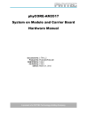
Fig. 26-1. GPIO Expansion Connector
shows the location of the GPIO expansion port connector X14. This connector provides a 1:1 mapping of most of the phyCORE-AM3517 mating connector X15 signals. Additional signals generated on the Carrier Board are also routed to the GPIO expansion port connector X14. As an accessory, a GPIO
Expansion Board (part # PCM-988) is made available through PHYTEC to mate with the X14 connector on the phyCORE-AM3517 Carrier Board. This Expansion Board provides a patch field for easy access to all signals, plus additional board space for testing and prototyping. A summary of the signal mappings
between X14, X15, and the patch field on the GPIO Expansion Board is provided in Part III .
© PHYTEC America LLC 2012 72
advertisement
* Your assessment is very important for improving the workof artificial intelligence, which forms the content of this project
Related manuals
advertisement
Table of contents
- 11 Part I: PCM-048/phyCORE-AM3517 System on Module
- 12 1 Introduction
- 14 1.1 Block Diagram
- 15 1.2 View of the phyCORE-AM
- 17 2 Pin Description
- 29 3 Jumpers
- 32 3.1 Jumper Settings
- 35 4 Power
- 35 4.1 Primary System Power (VIN & VIN_3V3)
- 35 4.2 Secondary Battery Power (VBAT)
- 35 4.3 PMIC Supplies (U2)
- 36 4.4 RTC Supplies (U2)
- 36 4.5 Selecting Shunt Resistors for Current Measurements
- 36 4.6 Voltage Supervisor (U2, U21)
- 38 5 External RTC (U22)
- 39 6 System Configuration and Booting
- 42 6.1 Boot Process
- 43 7 System Memory
- 43 7.1 SDRAM (U8, U9)
- 43 7.2 NAND Flash (U16)
- 44 7.3 EEPROM (U13)
- 44 7.4 Memory Map
- 45 8 Serial Interfaces
- 45 8.1 RS-232 Transceiver (U15)
- 45 8.2 Ethernet PHY (U12)
- 45 8.3 USB OTG (U1)
- 46 8.4 USB1 Host (U1, U7)
- 47 9 Debug Interface (X1)
- 48 10 Touch Screen Controller (U25)
- 49 11 General Purpose Memory Controller (U2)
- 50 12 LCD LVDS Transmitter
- 51 12.1 LVDS and SOM I/O Voltage (J23)
- 52 13 AM3517 IO and GPMC Bus Voltage
- 53 14 Technical Specifications
- 55 15 Hints for Handling the phyCORE-AM
- 56 Part II: PCM-961/phyCORE-AM3517 Carrier Board
- 57 16 Introduction
- 58 17 Overview of Peripherals
- 61 18 Jumpers
- 65 19 phyCORE-AM3517 SOM Connectivity
- 66 20 Power
- 66 20.1 Wall Adapter Input (X9)
- 67 20.2 Power over Ethernet (PoE)
- 68 20.3 Lithium-Ion Battery
- 68 20.4 3.3V Supply (U27)
- 68 20.5 1.8V Supply (U31)
- 69 20.6 Current Measurement
- 70 21 JTAG Connectivity
- 72 22 Audio Interface
- 74 23 Ethernet Connectivity
- 75 24 USB Connectivity
- 77 25 LCD and DVI Connectivity
- 80 25.1 DVI Connector
- 80 25.2 LVDS Connectors
- 81 25.3 TTL LCD Connector
- 82 26 GPIO Expansion Connector
- 83 27 RS-232 Connectivity
- 87 28 SD/SDIO/MMC Connectivity
- 89 29 CAN (Controller Area Network) Interface
- 90 30 Wireless Connector
- 92 31 TV Out
- 93 32 Camera Interface
- 95 33 User Buttons
- 97 34 User LEDs
- 98 35 Boot Mode Selection
- 102 36 System Reset Button
- 103 Part III
- 103 Part III: PCM-988/GPIO Expansion Board
- 104 37 Introduction
- 106 38 System Signal Mapping
- 107 39 GPMC Signal Mapping
- 109 40 UART Signal Mapping
- 110 41 I²C Signal Mapping
- 111 42 GPIO Signal Mapping
- 112 43 USB Signal Mapping
- 113 44 CAN Signal Mapping
- 114 45 Ethernet Signal Mapping
- 115 46 HDQ Signal Mapping
- 116 47 McBSP Signal Mapping
- 117 48 SPI Signal Mapping
- 118 49 Power Signal Mapping
- 119 Revision History