- Industrial & lab equipment
- Electrical equipment & supplies
- Power conditioning
- Power supply units
- Alpha
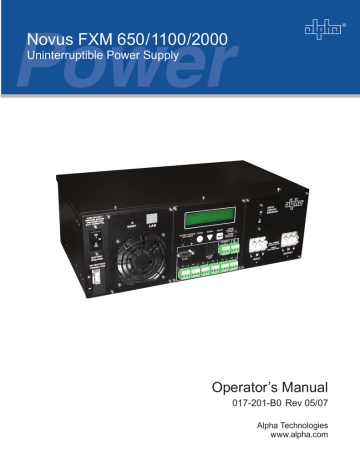
- Novus FXM 650
- User manual
advertisement

FXM UPS Operator's Manual
3.5 Making Measurements
The system status menu (Figure 3.5.1) lets you make measurements of various UPS inputs, outputs, temperatures and other values. You can also use the Novus User Software to make these measurements (See Section 4.6, “Novus User Software”).
Procedure
1. From the logo screen (Figure 3.1.1) go to the system status menu (Figure 3.1.3).
STATUS
MENUS
120/60/N
LINE
2. Press the SELECT button to enter the submenu (Figure 3.5.1).
CANCEL SCROLL SELECT
3. Press the SCROLL button to move between items in the submenu. When you reach the item you want to measure, stop pressing the button.
The measurement is automatically displayed on the LCD. It is automatically updated every 0.5 second (VIN shown).
Measurement Finished
VIN
120V
120/60/N
LINE
26
LCD Shows
VIN
VOUT
IOUT AC
BATT TEMP
FREQ IN
OUTPUT PWR
BATT VOLT
CHGR CUR
System Status Menu
Meaning
Input Voltage
Description
The line input voltage into the UPS.
Output Voltage The UPS’s output voltage (true RMS).
Output Current (AC) The UPS’s AC output current (true RMS).
Battery Temperature The battery’s temperature (°C).
Input Frequency The frequency of line power into the UPS (Hz).
Output Power
Battery Voltage
Charger Current
The UPS’s output power in VA (true RMS).
The battery’s output voltage (VDC).
The UPS’s battery charging current is set to this value (Amps).
Figure 3.5.1
System Status Menu
Doc# 017-201-B0 Rev 05/07
Operation
DATE
TIME
INV COUNT
INV TIMER
SHED TIMER1
SHED TIMER2
SHED TIMER3
VERSION
Date
Time
Inverter Count
Inverter Time
Amount of time until the dry contact is activated.
Software Version
System Status Menu
The date and time (24 hour clock).
The number of times the UPS was in inverter mode.
The total amount of time the UPS was in inverter mode.
The factory default dry contact for this setting is contact C4. SHED TIMER2 and SHED
TIMER3 can be field programmed (See Section 4.4.2, “Setting the Timer Contact”). This display shows the amount of time left (in seconds) until the contact is activated. The factory default setting is 2 hours, but this can be changed as shown in Section 4.4.2.
The software version used in this UPS.
Figure 3.5.1
System Status Menu (Continued)
Doc# 017-201-B0 Rev 05/07 27
advertisement
* Your assessment is very important for improving the workof artificial intelligence, which forms the content of this project
Related manuals
advertisement
Table of contents
- 5 1 Introduction
- 6 1.1 Safety Checklists
- 6 1.1.1 UPS Safety Checklist
- 7 1.1.2 Battery Safety Checklist
- 8 1.2 Unpacking and Inspection Checklist
- 9 1.3 The FXM Front Panel
- 15 2 Installation
- 16 2.1 Site Preparation Checklists
- 17 2.2 Mounting the UPS
- 18 2.3 Wiring the External Batteries
- 20 2.4 Wiring the UPS
- 21 2.5 ATS/GTS Option
- 22 3 Operation
- 23 3.1 Operating the Control Panel
- 25 3.2 Turning the UPS On and Off
- 27 3.3 Replacing the Batteries
- 28 3.4 Operating the UPS
- 30 3.5 Making Measurements
- 32 3.6 Troubleshooting the UPS
- 34 3.7 Viewing the 25-Event Log
- 35 4 Communication
- 36 4.1 Wiring the RS-232 Port
- 37 4.2 Using the Main Menu
- 37 4.2.1 Main Menu Screen
- 38 4.2.2 RS-232 Menu Tree
- 39 4.2.3 Line Status
- 39 4.2.4 Output Status
- 40 4.2.5 Fault and Alarm Displays
- 41 4.3 Adjusting and Controlling the UPS
- 42 Clock
- 42 4.4.1 Programming the Dry Contacts
- 43 4.4.2 Setting the Timer Contact
- 43 4.4.3 Setting the Date and Time
- 44 4.5 100-Event Log
- 45 4.6 Novus User Software
- 45 4.6.1 Introduction
- 45 for the .NET Framework
- 46 4.6.3 Installation and Set Up
- 47 4.6.4 Operation
- 50 5 Maintenance
- 51 5.1 Updating the Software
- 53 Specifications
- 55 Index
- 58 Warrant