- No category
advertisement
ICP DAS PMC-5151 User Manual
3 System Login
When connect to PMC-5151 webpage server via Web browser ( IE 8 / Firefox 3.6 /
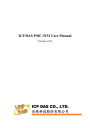
Chrome 14.0.8 version or above are recommended ), in order to get a better operation experience, 1280x1024 resolution is recommended. The Login page of PMC-5151 is shown as below:
Figure3-1 : PMC-5151 Login page
By inputing different passwards, two levels of authority are granted as follow:
Administrator (Default password:
Admin )
Login as an administrator allows performing settings and reviewing of system information, power meter information and I/O modules information, it also allows performing Logic rule edition. Only one administrator is allowded to login into the system at the same time.
General User (Default password:
User )
General users are allowed to view power meter data and I/O module information only; they are not allowed to perform any settings. It allows maximum 5 general users to login and get into the system at the same time.
Select your preferred language from the dropdown list in the “Language” field for the
Web page user interface (English, Traditional Chinese, Simplified Chinese). After login into the system, if the user want to change the language again, logout and re-select the language on the Login page.
Please note: Before starting the system, please make sure the browser you are using already enable JavaScript support and has the latest version of Adobe Flash Player installed, otherwise the system will not function properly.
5
ICP DAS PMC-5151 User Manual
4 System Main Page
After login into the system, PMC-5151 default home page will be displayed, and will automatically read settings of the PMC-5151 to the webpage.
A
B
C
Figure4-1 : PMC-5151 Main Page
PMC-5151 main page could be divided into 3 areas:
A. System function area
B. Sub-function area
C. Data review/System setting area
More detailed information for each area will be given in the following section.
6
advertisement
* Your assessment is very important for improving the workof artificial intelligence, which forms the content of this project
Related manuals
advertisement
Table of contents
- - PMC-5151 Introduction
- - Before Installation
- - System Login
- - System Main Page
- - System function area
- - Rules management toolbar
- 3 Real-time information area
- 3 System function toolbar
- 4 Sub-function area
- 4 Data review/System setting area
- 7 Main Page
- 7 Power Meter Information
- 7 Power Meter Information Overview
- 11 Power Meter Statistics Information Overview
- 12 Other Information
- 12 I/O Information
- 13 Power Data Information
- 13 Overview
- 14 Group Overview
- 15 Realtime Chart
- 15 Power Meter Mode
- 17 Group Mode
- 19 Historical Chart
- 21 Historical Data Report
- 24 Historical Electricity Analysis
- 24 Electricity Usage Analysis of Trend
- 26 Electricity Usage Analysis of Time
- 29 Electricity Usage Analysis of Proportion
- 32 PUE Information
- 32 Real-Time
- 32 History
- 34 I/O Information
- 35 Event Log
- 36 HMI User-Defiend HMI
- 37 Polling Time Information
- 57 Modbus Table Information
- 58 UID Information
- 59 System Setting
- 60 Time Setting
- 62 Network Setting
- 63 VPN Setting
- 66 SNMP Setting
- 69 Security Setting
- 71 I/O Interface Setting
- 74 Other Setting
- 75 Power Meter Group Setting
- 75 Group and Subgroup Viewing
- 76 Group and Subgroup Setting
- 77 Group and Subgroup configuration
- 78 Setup the loops/phases of the subgroup
- 79 Loop/Phase of group configuration
- 80 Firmware Update
- 83 Power Meter / I/O Module Setting
- 84 Power Meter Setting
- 85 Scan to add Modbus RTU Power Meters
- 86 Add Modbus RTU Power Meter manually
- 88 Add Modbus TCP Power Meter manually
- 89 Power Meter List Interface
- 90 Modbus RTU Powe Meter Setting
- 93 Modbus TCP Powe Meter Setting
- 95 XW-Board Setting
- 95 XW-Board DI Channel Settings
- 96 XW-Board DO Channel Settings
- 98 XW-Board AI Channel Settings
- 101 XW-Board AO Channel Settings
- 102 I/O Module Setting
- 102 Scan to Add ICP DAS M-7000 Modules
- 105 Add Modbus RTU Module (or M-7000 Module) manually
- 106 Add Modbus TCP Module manually
- 107 I/O Module List Interface
- 108 M-7000 Module Setting
- 113 Modbus RTU Module Setting
- 125 Modbus TCP Module Setting
- 127 Logger Setting
- 128 Data Logger Setting
- 131 Event Logger Setting
- 131 FTP Upload Setting
- 133 The Path of Data Log File
- 135 The format of the Power Data Logger file
- 137 The format of the Power Report file
- 140 The Format of User-Defined Data File
- 141 Advanced Setting
- 141 Email Setting
- 144 SMS Setting
- 145 SMS Alarm Setting
- 147 SMS Command Setting
- 151 SNMP Trap Setting
- 156 Timer Setting
- 158 Schedule Setting
- 161 PUE Setting
- 162 Internal Register Setting
- 164 Flash HMI Setting
- 167 IF Condition Setting
- 168 ICP DAS Module
- 172 Modbus Module
- 175 Power Meter
- 175 Connection Status
- 176 Timer
- 177 Schedule
- 177 FTP Upload Status
- 178 SD Card Status
- 178 Rule Status
- 179 THEN/ELSE Action Setting
- 180 ICP DAS Module
- 184 Modbus Module
- 185 Power Meter
- 186 Timer
- 186 Email
- 187 SMS Alarm
- 189 SNMP Trap
- 190 Data Logger
- 190 Rule Status
- 192 Appendix I:Modbus Address Table
- 266 Appendix III:Setup the GTM-201-USB with PMC
- 270 Appendix IV:The configuration setting of M-7000 module
- 274 Appendix V:The AI Channel setting of XW310C
- 275 Appendix VI:The SNMP Variables for PMC