- No category
advertisement
ICP DAS PMC-5151 User Manual
6.2 Network Setting
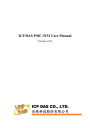
Network Setting allows making a change to network configuration, web server port or Modbus settings on the PMC-5151. The following figure illustrates the configuration interface:
Figure6-4 : Network Setting Page
Each time when the user enters this page, it will read and display current network configuration (LAN1/LAN2) and port settings from the PMC-5151.
In the “Network Settings” section, the user can modify IP/Mask/
Gateway/DNS Server IP configuration. After all settings are completed, click “Save” button to save the changes. After the network configuration is completed, the user could login into PMC-5151 webpage via LAN1 or
LAN2, and is able to retrieve data via Modbus TCP. In the “Port Setting” section, the user can modify the Web Server Port/ Modbus TCP Port/
Modbus NetID. After all settings are completed, click “Save” button to save the changes.
50
advertisement
* Your assessment is very important for improving the workof artificial intelligence, which forms the content of this project
Related manuals
advertisement
Table of contents
- - PMC-5151 Introduction
- - Before Installation
- - System Login
- - System Main Page
- - System function area
- - Rules management toolbar
- 3 Real-time information area
- 3 System function toolbar
- 4 Sub-function area
- 4 Data review/System setting area
- 7 Main Page
- 7 Power Meter Information
- 7 Power Meter Information Overview
- 11 Power Meter Statistics Information Overview
- 12 Other Information
- 12 I/O Information
- 13 Power Data Information
- 13 Overview
- 14 Group Overview
- 15 Realtime Chart
- 15 Power Meter Mode
- 17 Group Mode
- 19 Historical Chart
- 21 Historical Data Report
- 24 Historical Electricity Analysis
- 24 Electricity Usage Analysis of Trend
- 26 Electricity Usage Analysis of Time
- 29 Electricity Usage Analysis of Proportion
- 32 PUE Information
- 32 Real-Time
- 32 History
- 34 I/O Information
- 35 Event Log
- 36 HMI User-Defiend HMI
- 37 Polling Time Information
- 57 Modbus Table Information
- 58 UID Information
- 59 System Setting
- 60 Time Setting
- 62 Network Setting
- 63 VPN Setting
- 66 SNMP Setting
- 69 Security Setting
- 71 I/O Interface Setting
- 74 Other Setting
- 75 Power Meter Group Setting
- 75 Group and Subgroup Viewing
- 76 Group and Subgroup Setting
- 77 Group and Subgroup configuration
- 78 Setup the loops/phases of the subgroup
- 79 Loop/Phase of group configuration
- 80 Firmware Update
- 83 Power Meter / I/O Module Setting
- 84 Power Meter Setting
- 85 Scan to add Modbus RTU Power Meters
- 86 Add Modbus RTU Power Meter manually
- 88 Add Modbus TCP Power Meter manually
- 89 Power Meter List Interface
- 90 Modbus RTU Powe Meter Setting
- 93 Modbus TCP Powe Meter Setting
- 95 XW-Board Setting
- 95 XW-Board DI Channel Settings
- 96 XW-Board DO Channel Settings
- 98 XW-Board AI Channel Settings
- 101 XW-Board AO Channel Settings
- 102 I/O Module Setting
- 102 Scan to Add ICP DAS M-7000 Modules
- 105 Add Modbus RTU Module (or M-7000 Module) manually
- 106 Add Modbus TCP Module manually
- 107 I/O Module List Interface
- 108 M-7000 Module Setting
- 113 Modbus RTU Module Setting
- 125 Modbus TCP Module Setting
- 127 Logger Setting
- 128 Data Logger Setting
- 131 Event Logger Setting
- 131 FTP Upload Setting
- 133 The Path of Data Log File
- 135 The format of the Power Data Logger file
- 137 The format of the Power Report file
- 140 The Format of User-Defined Data File
- 141 Advanced Setting
- 141 Email Setting
- 144 SMS Setting
- 145 SMS Alarm Setting
- 147 SMS Command Setting
- 151 SNMP Trap Setting
- 156 Timer Setting
- 158 Schedule Setting
- 161 PUE Setting
- 162 Internal Register Setting
- 164 Flash HMI Setting
- 167 IF Condition Setting
- 168 ICP DAS Module
- 172 Modbus Module
- 175 Power Meter
- 175 Connection Status
- 176 Timer
- 177 Schedule
- 177 FTP Upload Status
- 178 SD Card Status
- 178 Rule Status
- 179 THEN/ELSE Action Setting
- 180 ICP DAS Module
- 184 Modbus Module
- 185 Power Meter
- 186 Timer
- 186 Email
- 187 SMS Alarm
- 189 SNMP Trap
- 190 Data Logger
- 190 Rule Status
- 192 Appendix I:Modbus Address Table
- 266 Appendix III:Setup the GTM-201-USB with PMC
- 270 Appendix IV:The configuration setting of M-7000 module
- 274 Appendix V:The AI Channel setting of XW310C
- 275 Appendix VI:The SNMP Variables for PMC