3 Functional definition. Infineon CY8C4045LQI-S412, CY8C4045LQI-S413, CY8C4025AZI-S413T, CY8C4024LQI-S412, CY8C4025AZQ-S403, CY8C4024LQI-S403T, CY8C4025LQI-S412, CY8C4025LQI-S402T, CY8C4045LQI-S411, CY8C4024AXI-S412
Add to My manuals58 Pages
advertisement

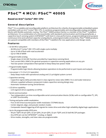
PSoC™ 4 MCU: PSoC™ 4000S
Based on Arm® Cortex®-M0+ CPU
Functional definition
3
3.1
Functional definition
CPU and memory subsystem
3.1.1
CPU
The Cortex®-M0+ CPU in the PSoC™ 4000S is part of the 32-bit MCU subsystem, which is optimized for low-power operation with extensive clock gating. Most instructions are 16 bits in length and the CPU executes a subset of the thumb-2 instruction set. It includes a nested vectored interrupt controller (NVIC) block with eight interrupt inputs and also includes a wakeup interrupt controller (WIC). The WIC can wake the processor from Deep Sleep mode, allowing power to be switched off to the main processor when the chip is in Deep Sleep mode.
The CPU also includes a debug interface, the serial wire debug (SWD) interface, which is a two-wire form of JTAG.
The debug configuration used for PSoC™ 4000S has four breakpoint (address) comparators and two watchpoint
(data) comparators.
3.1.2
Flash
The PSoC™ 4000S device has a flash module with a flash accelerator, tightly coupled to the CPU to improve average access times from the flash block. The low-power flash block is designed to deliver two wait-state (WS) access time at 48 MHz. The flash accelerator delivers 85% of single-cycle SRAM access performance on average.
3.1.3
SRAM
Four KB of SRAM are provided with zero wait-state access at 48 MHz.
3.1.4
SROM
A supervisory ROM that contains boot and configuration routines is provided.
3.2
System resources
3.2.1
Power system
The power system is described in detail in the section
“Power” on page 19. It provides assurance that voltage
levels are as required for each respective mode and either delays mode entry (for example, on power-on reset
(POR)) until voltage levels are as required for proper functionality, or generates resets (for example, on brown-out detection). The PSoC™ 4000S operates with a single external supply over the range of either 1.8 V ±5% (externally regulated) or 1.8 to 5.5 V (internally regulated) and has three different power modes, transitions between which are managed by the power system. The PSoC™ 4000S provides Active, Sleep, and Deep Sleep low-power modes.
All subsystems are operational in Active mode. The CPU subsystem (CPU, flash, and SRAM) is clock-gated off in
Sleep mode, while all peripherals and interrupts are active with instantaneous wake-up on a wake-up event. In
Deep Sleep mode, the high-speed clock and associated circuitry is switched off; wake-up from this mode takes
35 µs.
Datasheet 10 002-00123 Rev. *O
2022-07-28
PSoC™ 4 MCU: PSoC™ 4000S
Based on Arm® Cortex®-M0+ CPU
Functional definition
3.2.2
Clock system
The PSoC™ 4000S clock system is responsible for providing clocks to all subsystems that require clocks and for switching between different clock sources without glitching. In addition, the clock system ensures that there are no metastable conditions.
The clock system for the PSoC™ 4000S consists of the internal main oscillator (IMO), internal low-frequency oscillator (ILO), a 32 kHz watch crystal oscillator (WCO) and provision for an external clock. Clock dividers are provided to generate clocks for peripherals on a fine-grained basis. Fractional dividers are also provided to enable clocking of higher data rates for UARTs.
The HFCLK signal can be divided down to generate synchronous clocks for the analog and digital peripherals.
There are eight clock dividers for the PSoC™ 4000S, two of those are fractional dividers. The 16-bit capability allows flexible generation of fine-grained frequency values, and is fully supported in PSoC™ Creator.
HFCLK
IMO
External Clock
Divide By
2,4,8
ILO LFCLK
Prescaler
SYSCLK
HFCLK
Integer
Dividers
Fractional
Dividers
6X 16-bit
2X 16.5-bit
PSoC™ 4000S MCU clocking architecture Figure 3
3.2.3
IMO clock source
The IMO is the primary source of internal clocking in the PSoC™ 4000S. It is trimmed during testing to achieve the specified accuracy. The IMO default frequency is 24 MHz and it can be adjusted from 24 to 48 MHz in steps of
4 MHz. The IMO tolerance with Infineon-provided calibration settings is ±2%.
3.2.4
ILO clock source
The ILO is a very low power, nominally 40-kHz oscillator, which is primarily used to generate clocks for the watchdog timer (WDT) and peripheral operation in Deep Sleep mode. ILO-driven counters can be calibrated to the IMO to improve accuracy. Infineon provides a software component, which does the calibration.
3.2.5
Watch crystal oscillator (WCO)
The PSoC™ 4000S clock subsystem also implements a low-frequency (32-kHz watch crystal) oscillator that can be used for precision timing applications. The WCO block allows locking the IMO to the 32-kHz oscillator. The
WCO on PSoC™ 4000S series devices does not connect to the LFCLK or WDT. Due to this, RTC functionality is not supported.
Datasheet 11 002-00123 Rev. *O
2022-07-28
advertisement
Related manuals
advertisement
Table of contents
- 1 General description
- 1 Features
- 3 Table of contents
- 4 1 Development ecosystem
- 4 1.1 PSoC™ 4 MCU resources
- 5 1.2 ModusToolbox™ software
- 6 1.3 PSoC™ Creator
- 7 Block diagram
- 9 2 Functional description
- 10 3 Functional definition
- 10 3.1 CPU and memory subsystem
- 10 3.2 System resources
- 12 3.3 Analog blocks
- 12 3.4 Programmable digital blocks
- 13 3.5 Fixed function digital
- 14 3.6 GPIO
- 14 3.7 Special function peripherals
- 15 4 Pinouts
- 17 4.1 Alternate pin functions
- 19 5 Power
- 19 5.1 Mode 1: 1.8 V to 5.5 V external supply
- 20 5.2 Mode 2: 1.8 V ± 5% external supply
- 21 6 Electrical specifications
- 21 6.1 Absolute maximum ratings
- 22 6.2 Device level specifications
- 27 6.3 Analog peripherals
- 32 6.4 Digital peripherals
- 36 6.5 Memory
- 37 6.6 System resources
- 41 7 Ordering information
- 43 8 Packaging
- 44 8.1 Package diagrams
- 49 9 Acronyms
- 53 10 Document conventions
- 53 10.1 Units of measure
- 54 Revision history