advertisement

Twin Disc, Incorporated
Electrical Installation
Split Single Lever Control Head Stations in Twin Engine Installations
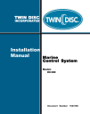
Some dual-engine installations use split Single Lever Control Heads at control stations rather than Dual Lever Control Heads. For such installations, one split lever harness and one dual lever harness are used. See Figure 32.
PORT STBD
TO EC300
STARBOARD CONTROL
STARBOARD
1020617
HARNESS, WIRING
DUAL LEVER
PORT
TO EC300
PORT CONTROL
1021458
HARNESS, WIRING
SPLIT LEVER
Figure 32. View of Split Single Lever Harness Wiring
Install the Control Head harnesses as follows:
Note: The Control Heads may be removed from the dash if this facilitates making the connection. If they are removed, then reinstall them after the connections have been made.
Note: Provide enough length in the harness to allow removal of the Control Heads in the future.
EC300 Marine Control System Installation Manual #1024168
71
Electrical Installation
72
Twin Disc, Incorporated
2.
3.
Refer to General Electrical Installation Guidelines for harness routing criteria.
1.
Connect the female circular connector end of the Split Lever harness with the two circular connectors to the port Single Lever Control Head.
Note: For each Control Head connector, align the large connector key with the large keyway and push the connector into place. Then, turn the connector’s collar until the engagement snap is felt.
4.
Route the Split Lever harness to the Starboard Control Head.
Connect the circular connector end of the Split Lever harness to the starboard Single Lever Control Head.
Connect the circular connector end of the Dual Lever harness to the male circular connector of the Split Lever harness at the Port Single
Lever Control Head.
5.
6.
7.
Ensure that the port and starboard single lever Control Heads are firmly mounted.
Route the Dual Lever harness to the EC300 Port Control and Starboard
Control.
Note: It is desirable, especially on single station vessels, to route the port and starboard harnesses as far apart as possible.
This minimizes the odds of both harnesses being accidently damaged at the same time allowing continued, but reduced, control of the vessel.
Connect the Dual Lever Harness plug labeled “Port” to the J1 receptacle of the Port EC300 Control.
8.
9.
Connect the Dual Lever Harness plug labeled “Starboard” to the J1 receptacle of the Starboard EC300 Control.
If applicable, repeat steps 1 through 6 for connecting additional Control
Stations using J2 for the second Control Head and J3 for the third Control
Head.
10.
If J2 and/or J3 are not used, install a connector kit into these receptacles to seal the connector. See System Drawing for Connector Plug Kit p/n.
11.
Secure all harnesses to a supporting structure with clamps or cable ties at 406 mm (16 in.) intervals.
EC300 Marine Control System Installation Manual #1024168
advertisement
Key Features
- Remote throttle control
- Transmission engagement control
- Engine Sync
- Trolling
- Shaft Brake
- Mechanical Actuator Output
- Transmission Oil Pressure and Oil Temperature Monitoring
- Helm Display
Related manuals
Frequently Answers and Questions
What types of vessels is the EC300 Marine Control System suitable for?
What types of engine/transmission combinations is the EC300 Marine Control System compatible with?
What are some of the special features of the EC300 Marine Control System?
advertisement